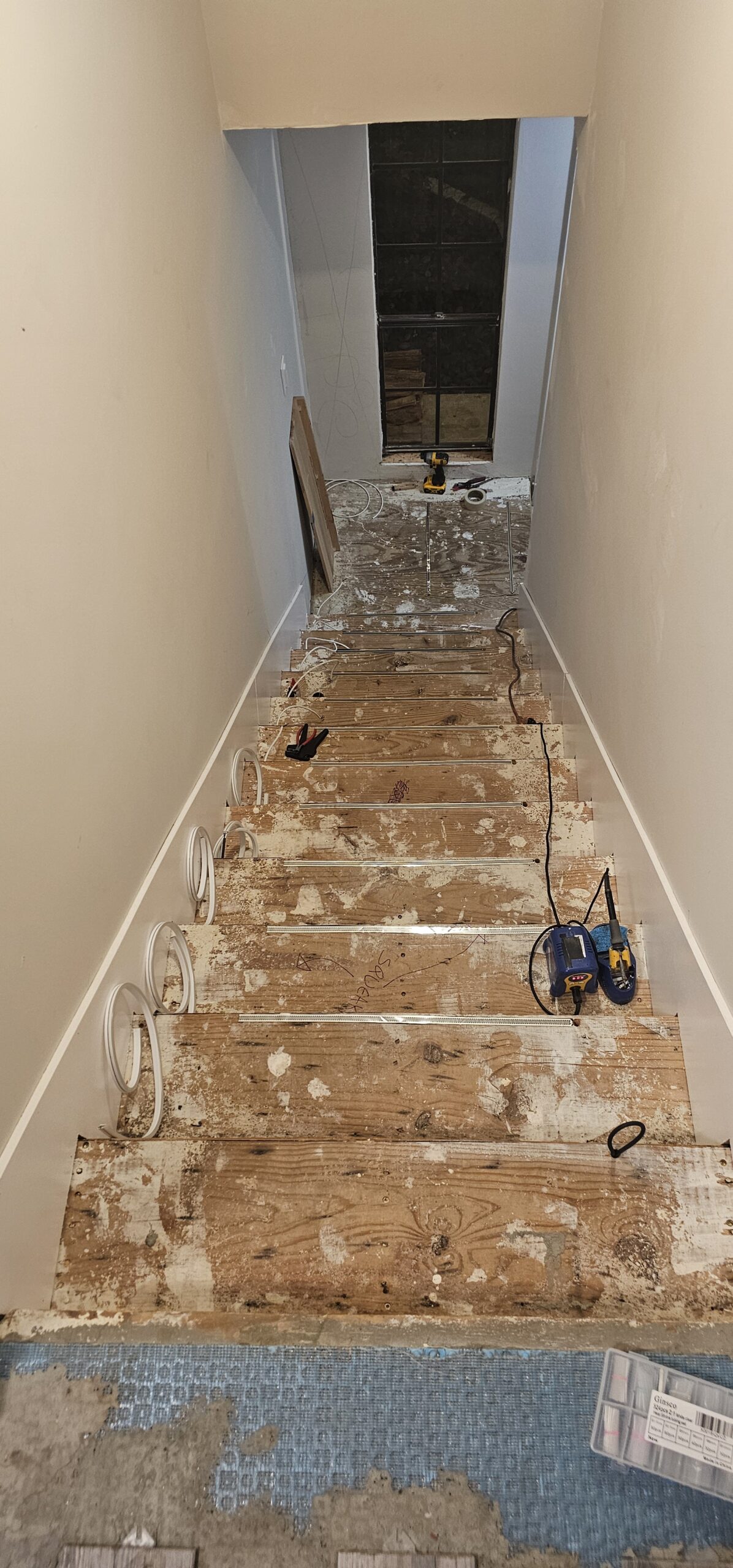
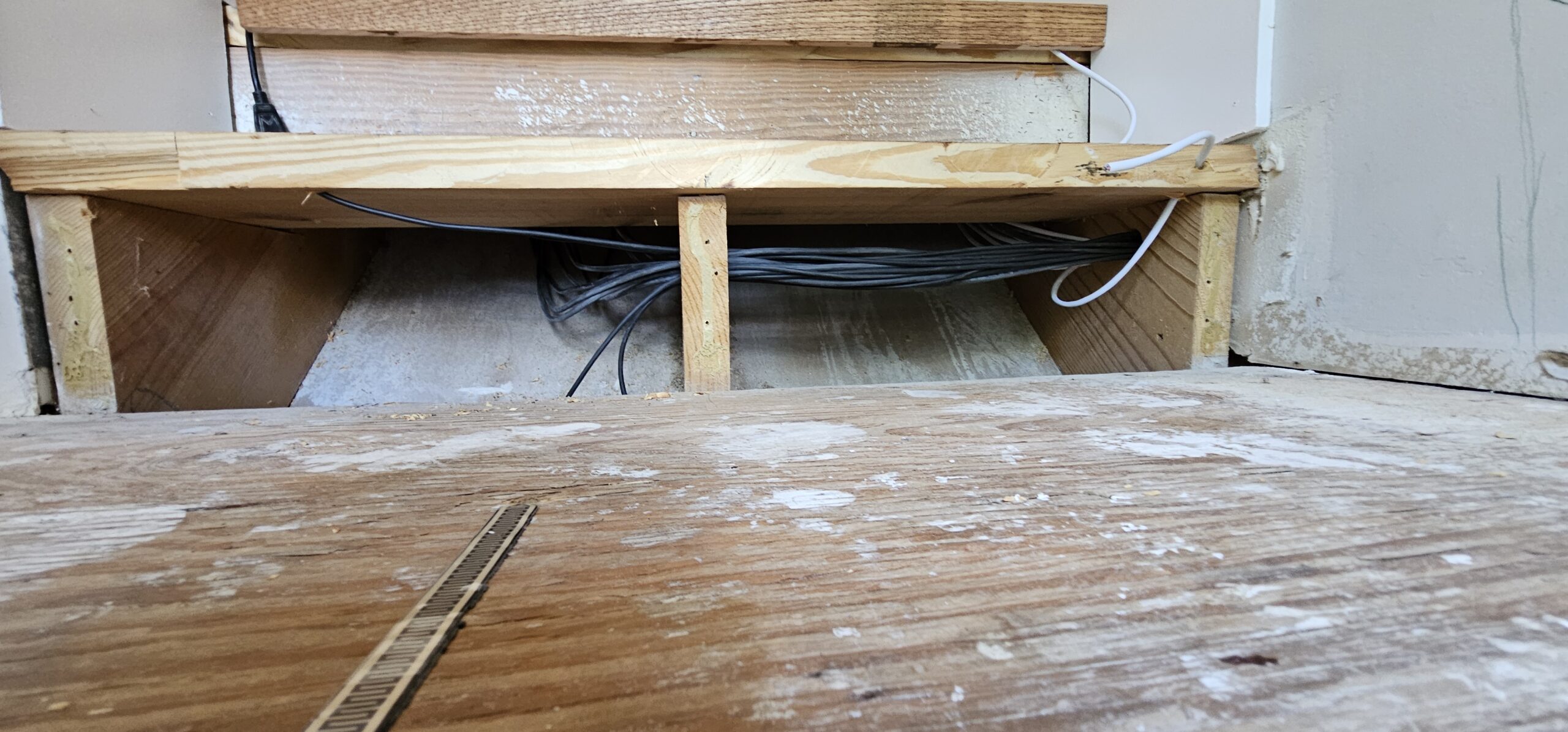
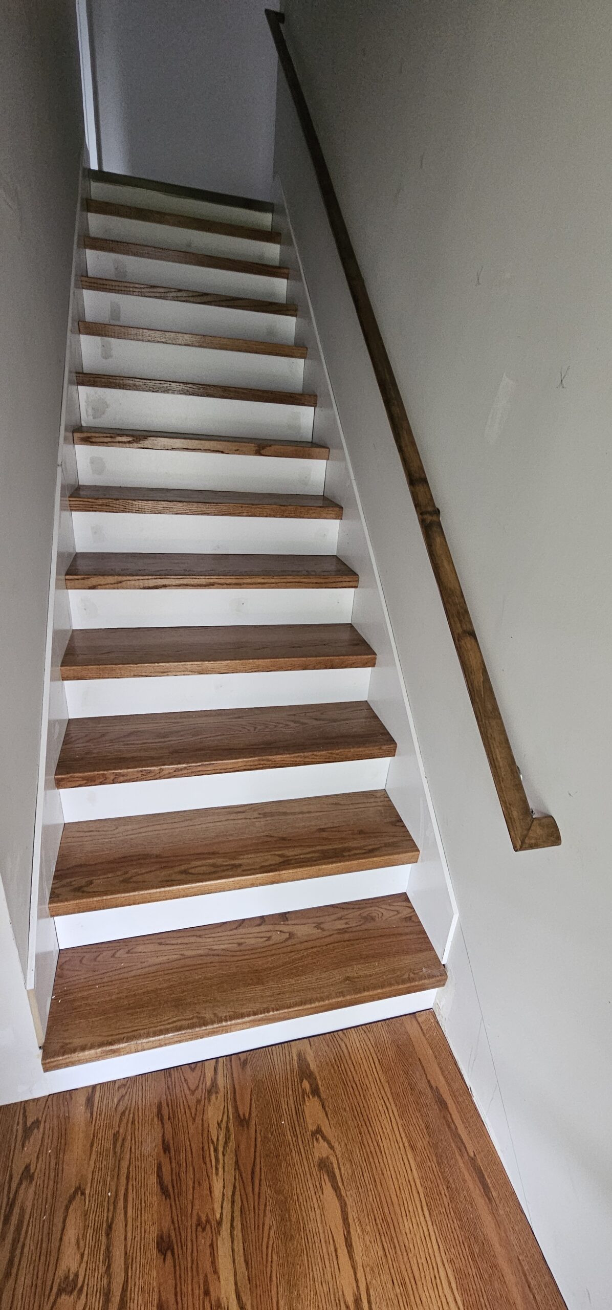
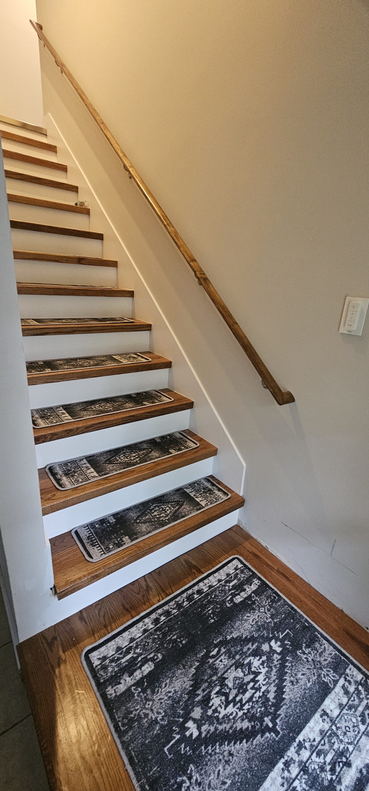
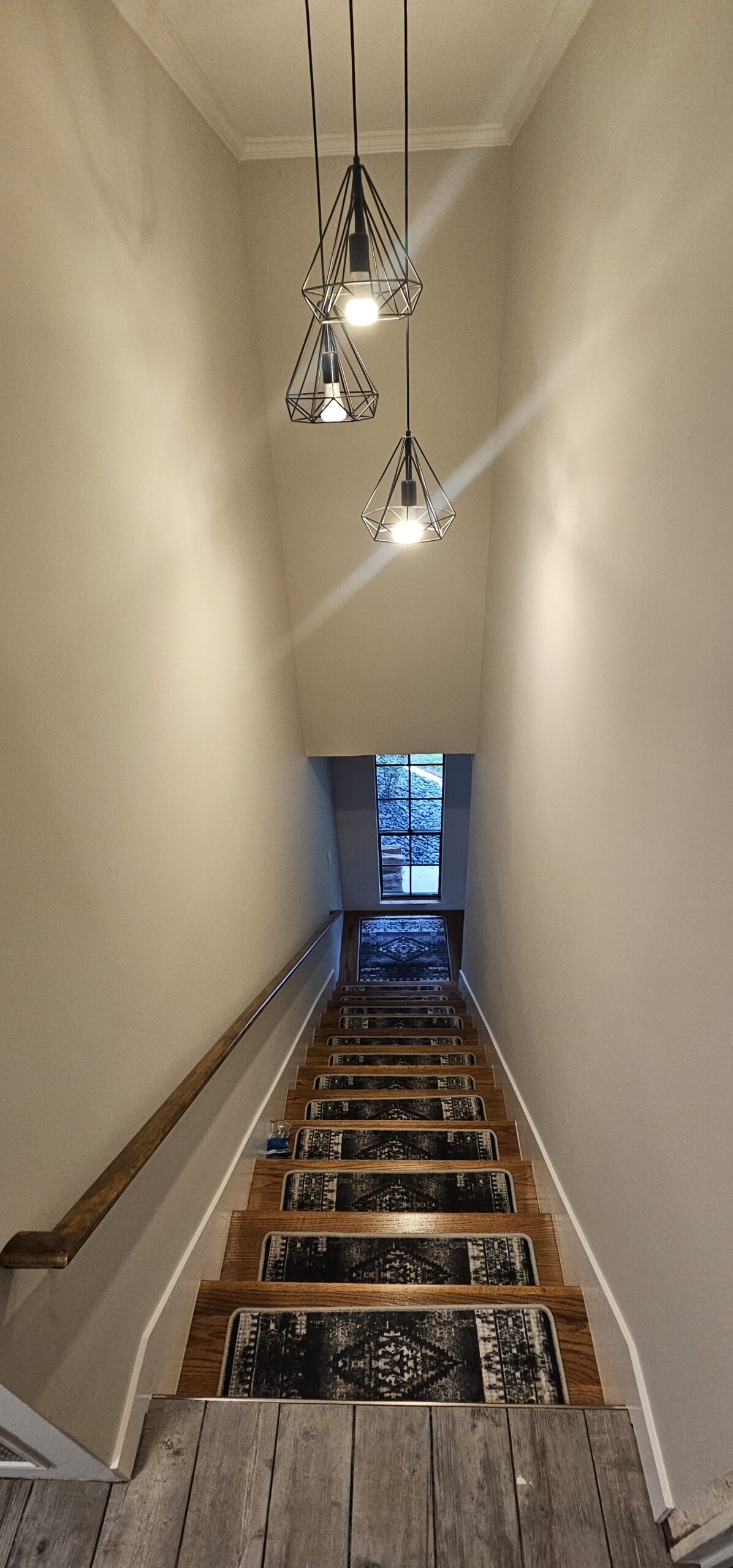
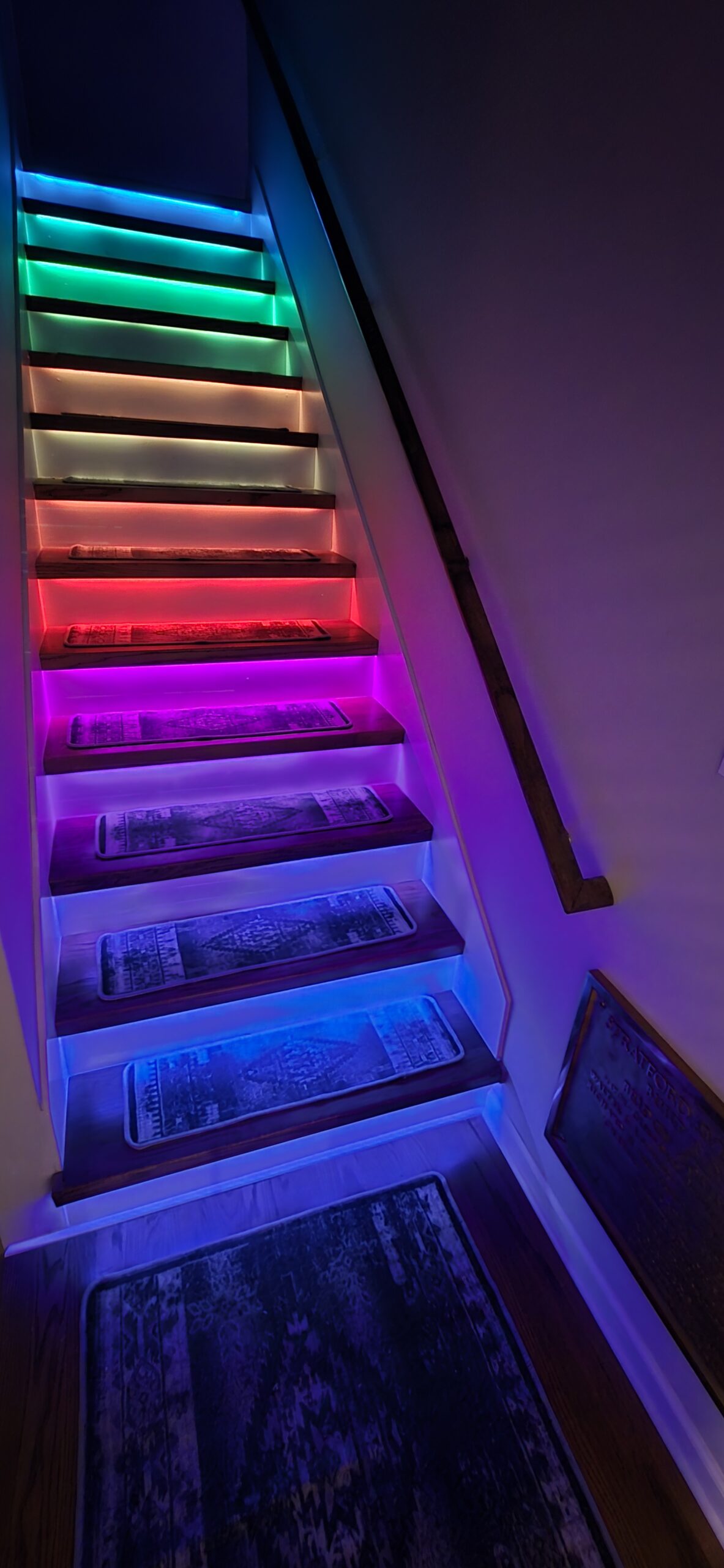
This was a big project but it turned out to be much easier than expected. The pressure switches were a bust but the LEDs strips work great. The stairs do not have enough play in them to trigger the pressure switches. I plan to use a distance sensor in leu of the switches.
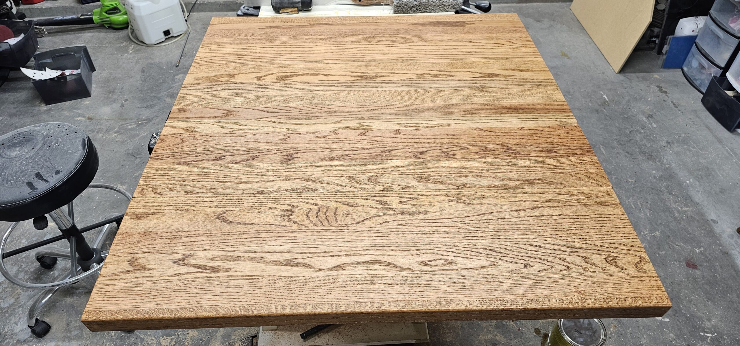
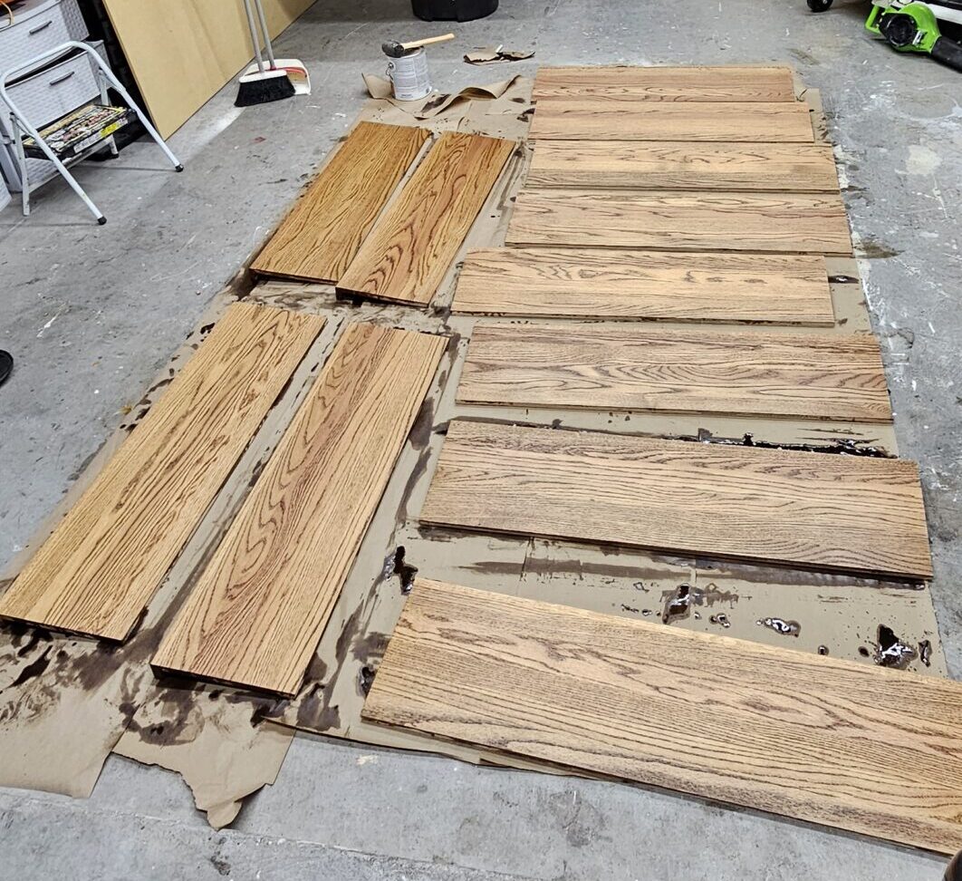
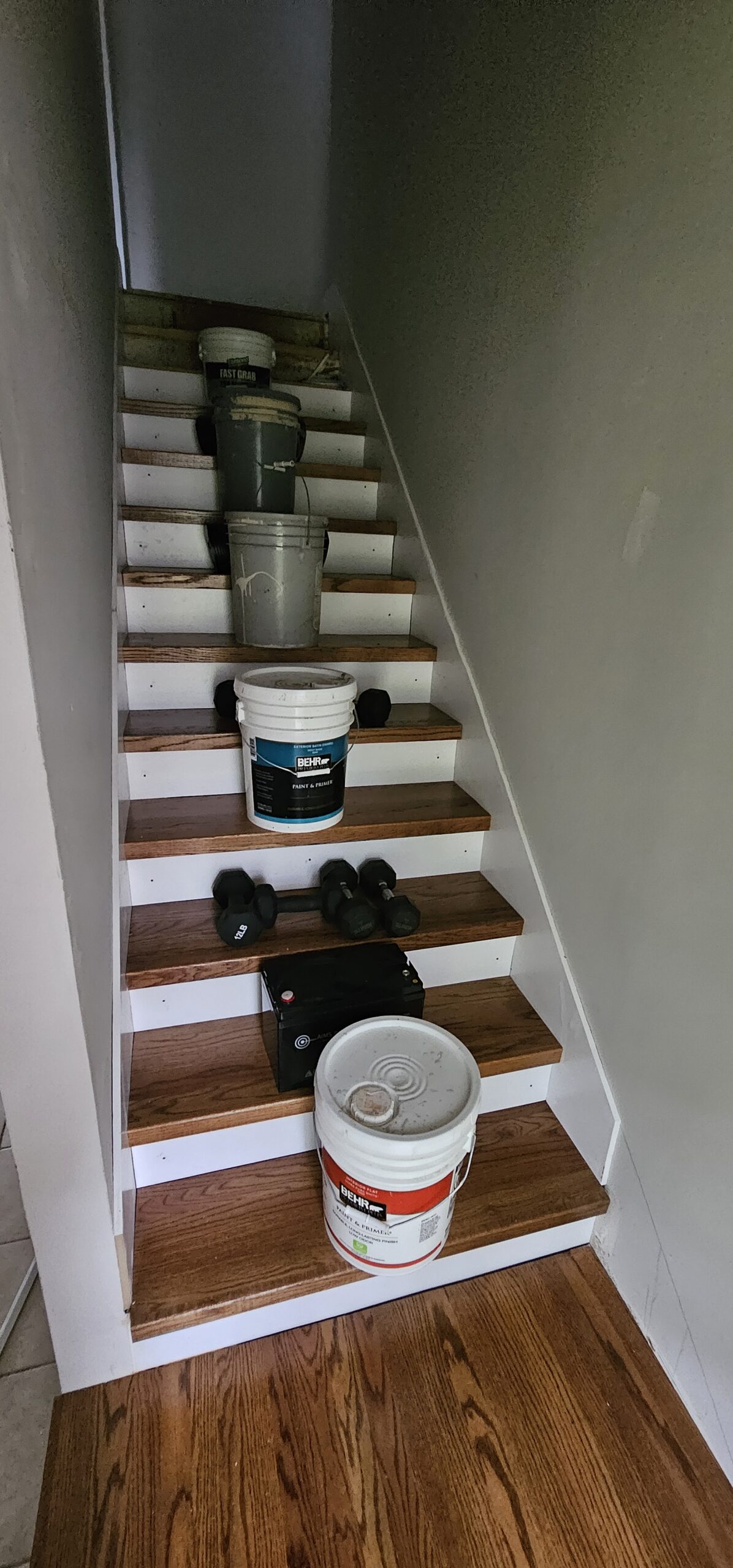
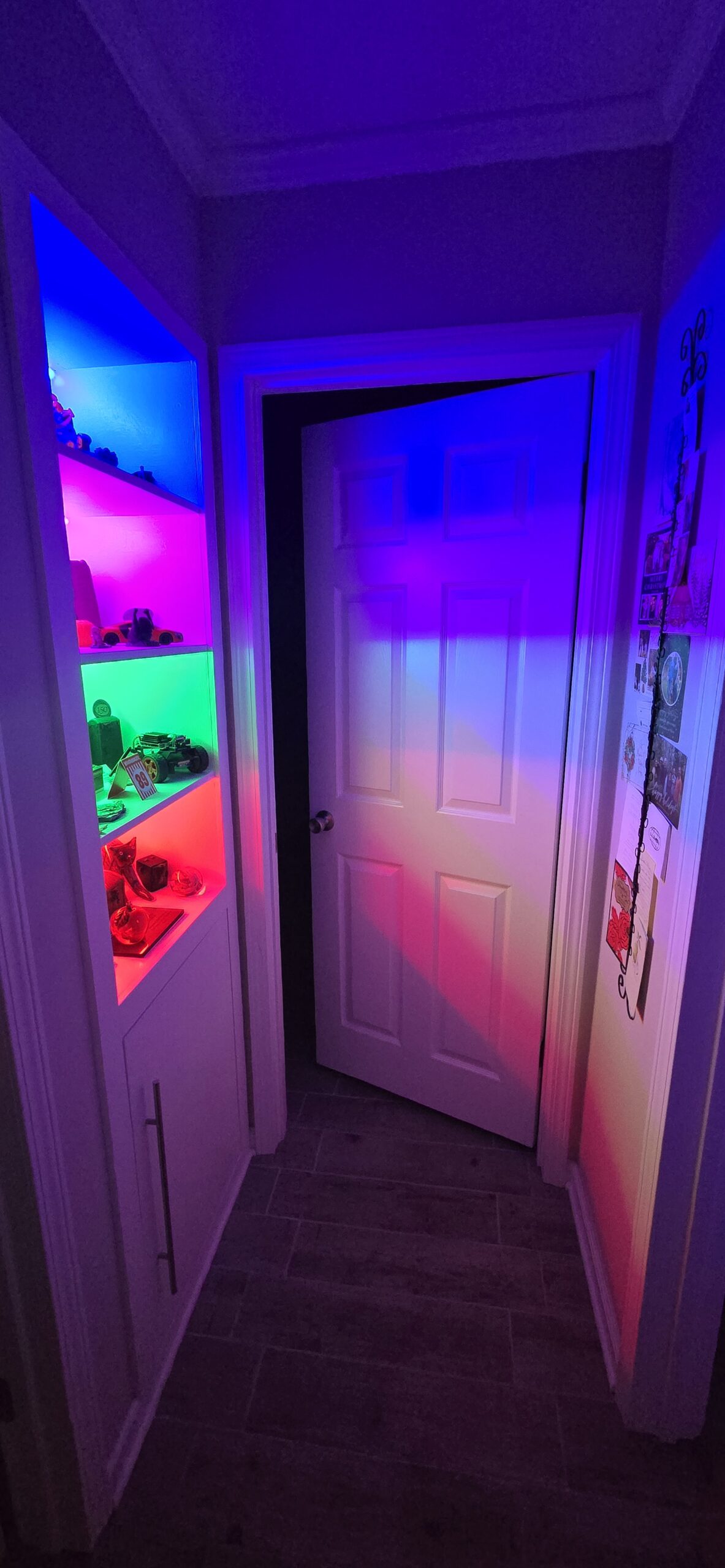
BeforePressure SensorLEDs, Sensors & Skirt BoardLots of wiresLanding glued upStain LandingStain TreadsSkirt BoardRugs So We Don’t SlipReplaced The LightAfter
I cant seem to find a picture of the before but I was able to snap this frame from a video I found. The outside did not look too bad but the inside was the main reason we replaced the whole thing. I will update this post if I find any footage from the inside.
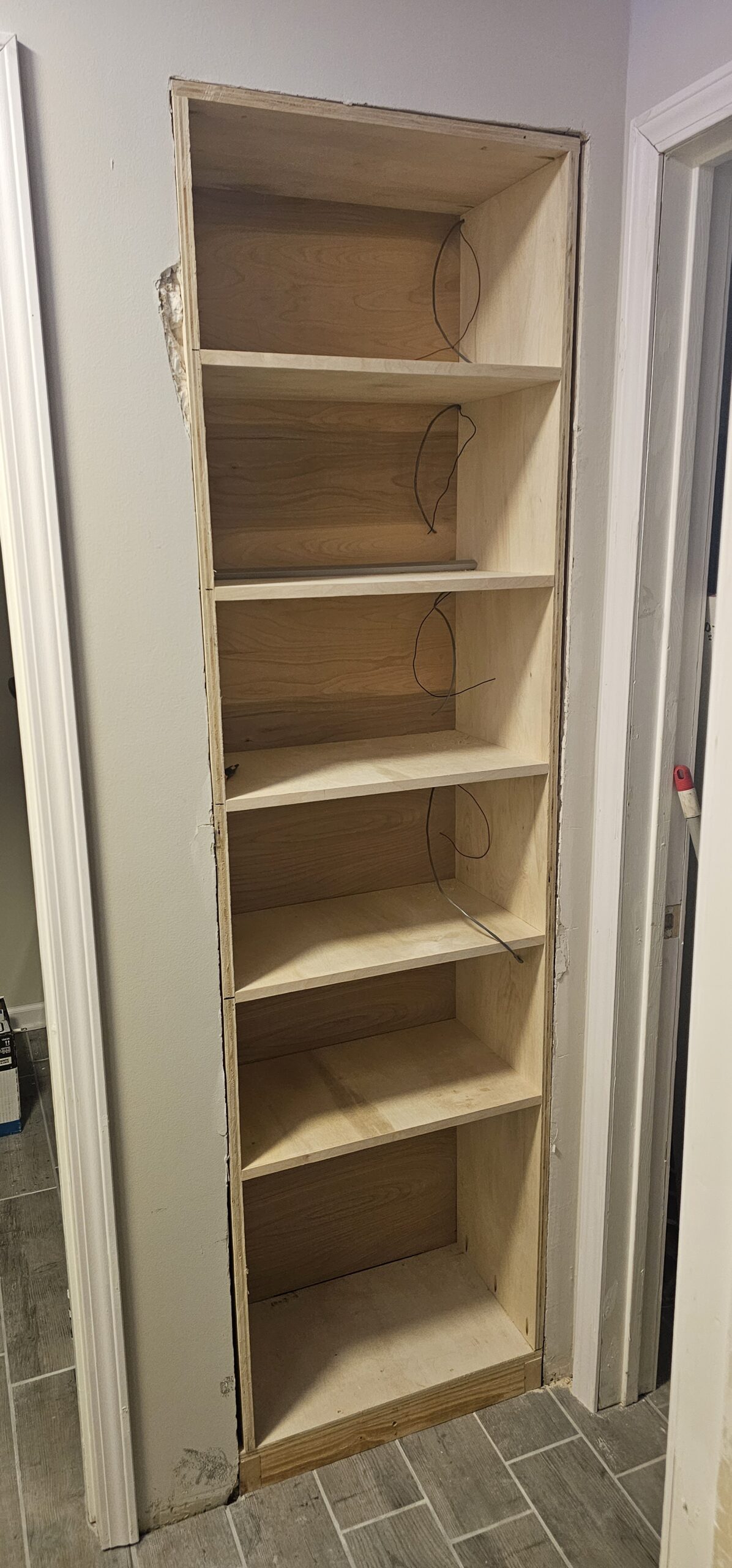
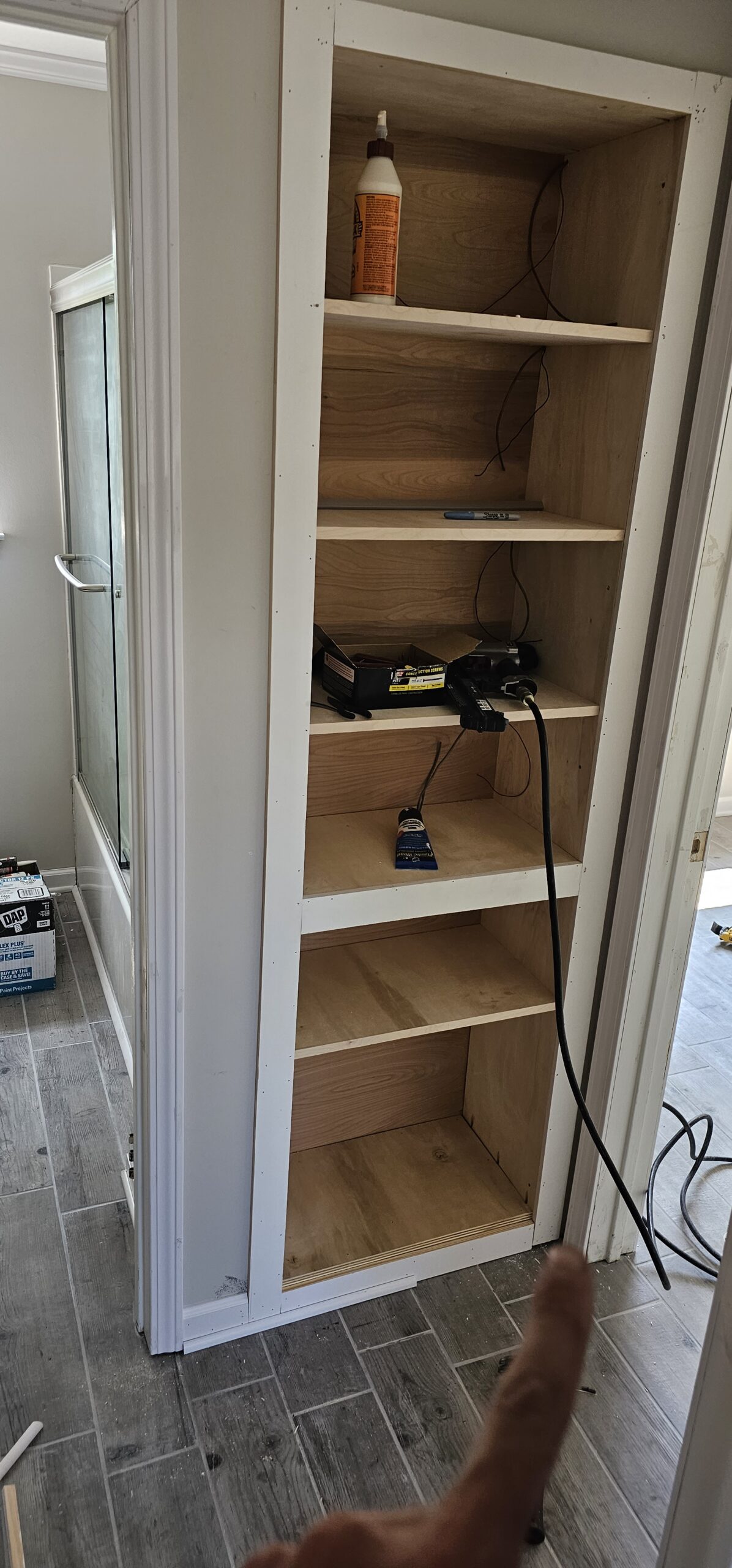
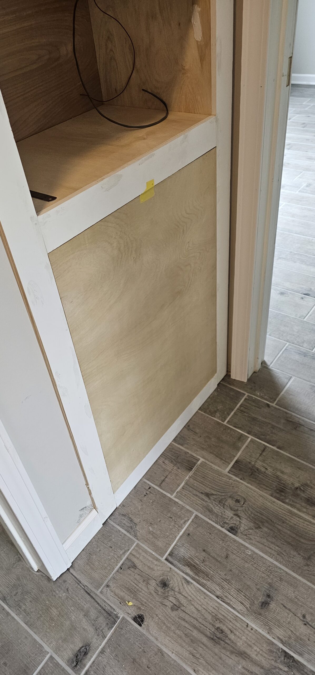
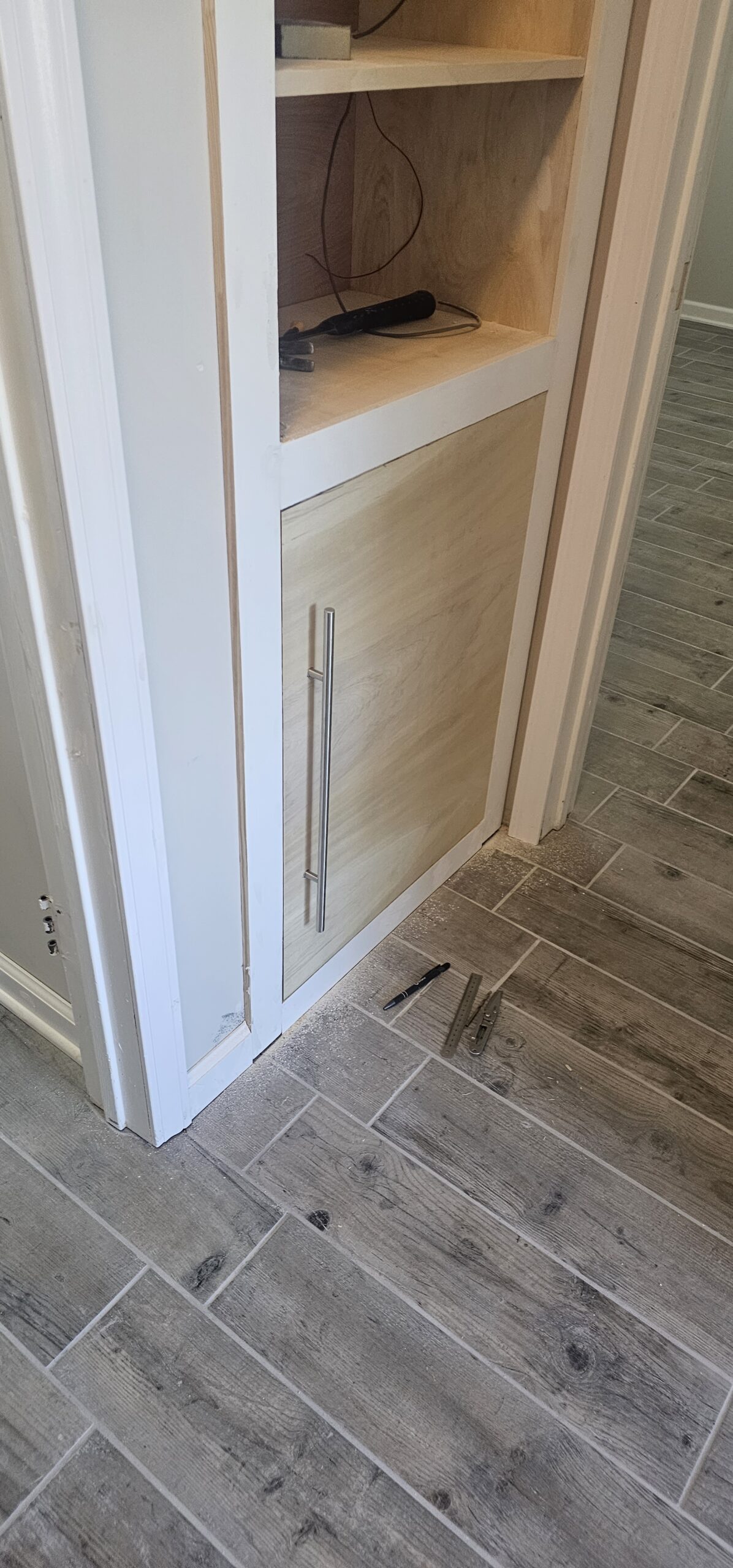
This was a simple build from a wood working stand-point. The whole unit was build downstairs in the workshop and dropped right place. Installed the molding, door, and paint.
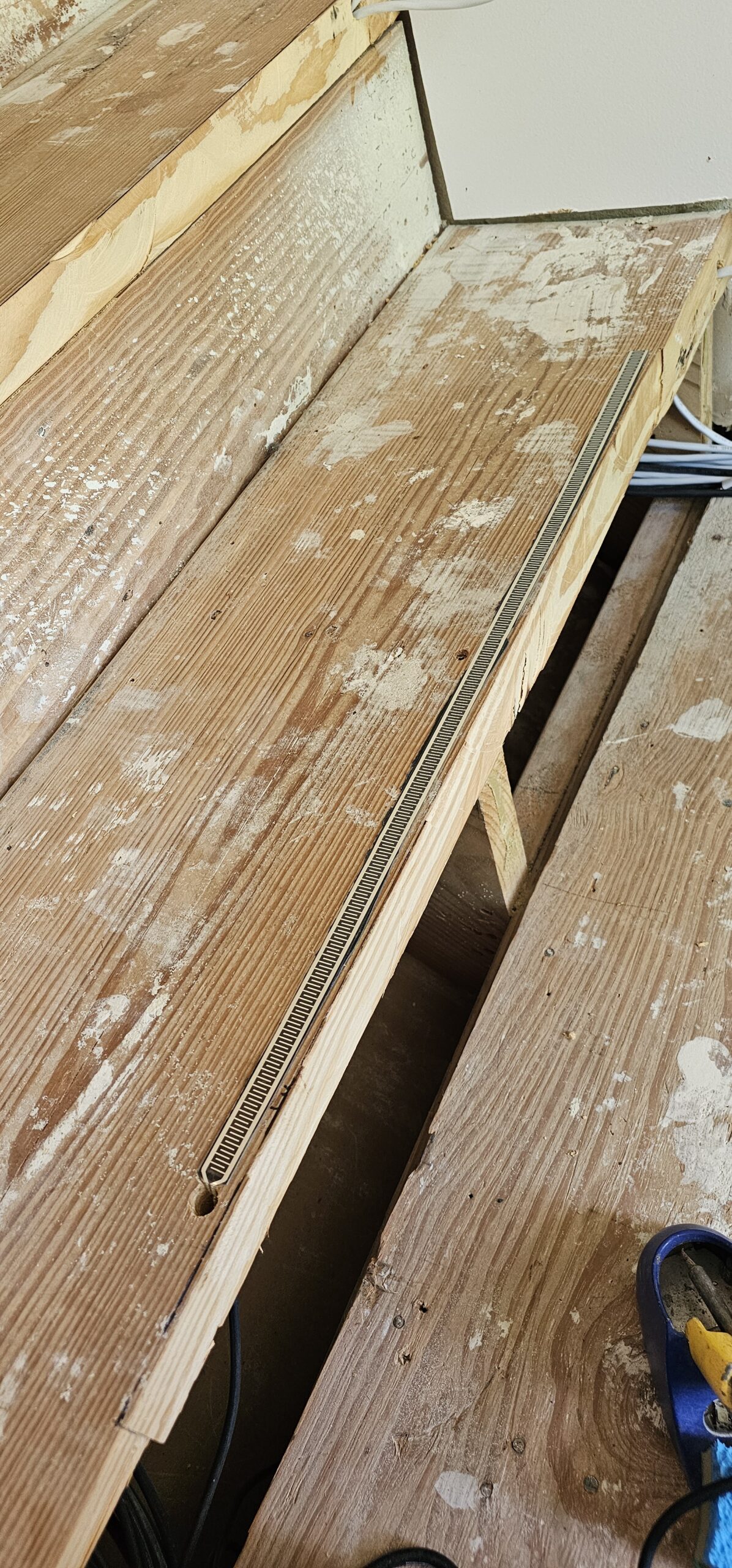
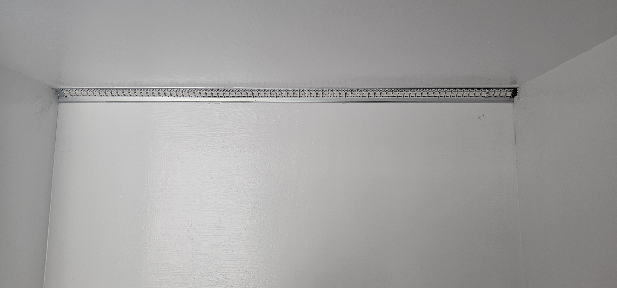
I pre-ran all the LED wires prior to installing the frame. This project used 144/m 5V Individual Addressable RGB WS2812B LED Strip. After this project, I moved to all 12V variants and stopped obsessing over controlling every single pixel. The 5V + 144/M + long wire runs initially gave me some issue, but I eventually over came them.
The LEDs sit in a quarter round defuser that I originally bought for the stairs. This was my test run for the stair project and I am happy with how they came out.
BeforeNew InsidesTrim ItTest Fit The DoorSame Style PullsDat DenseCover Up!After SideAfter Side
I made a bunch of progress but I also added to my to-do list; 🤦 I tend to do that.
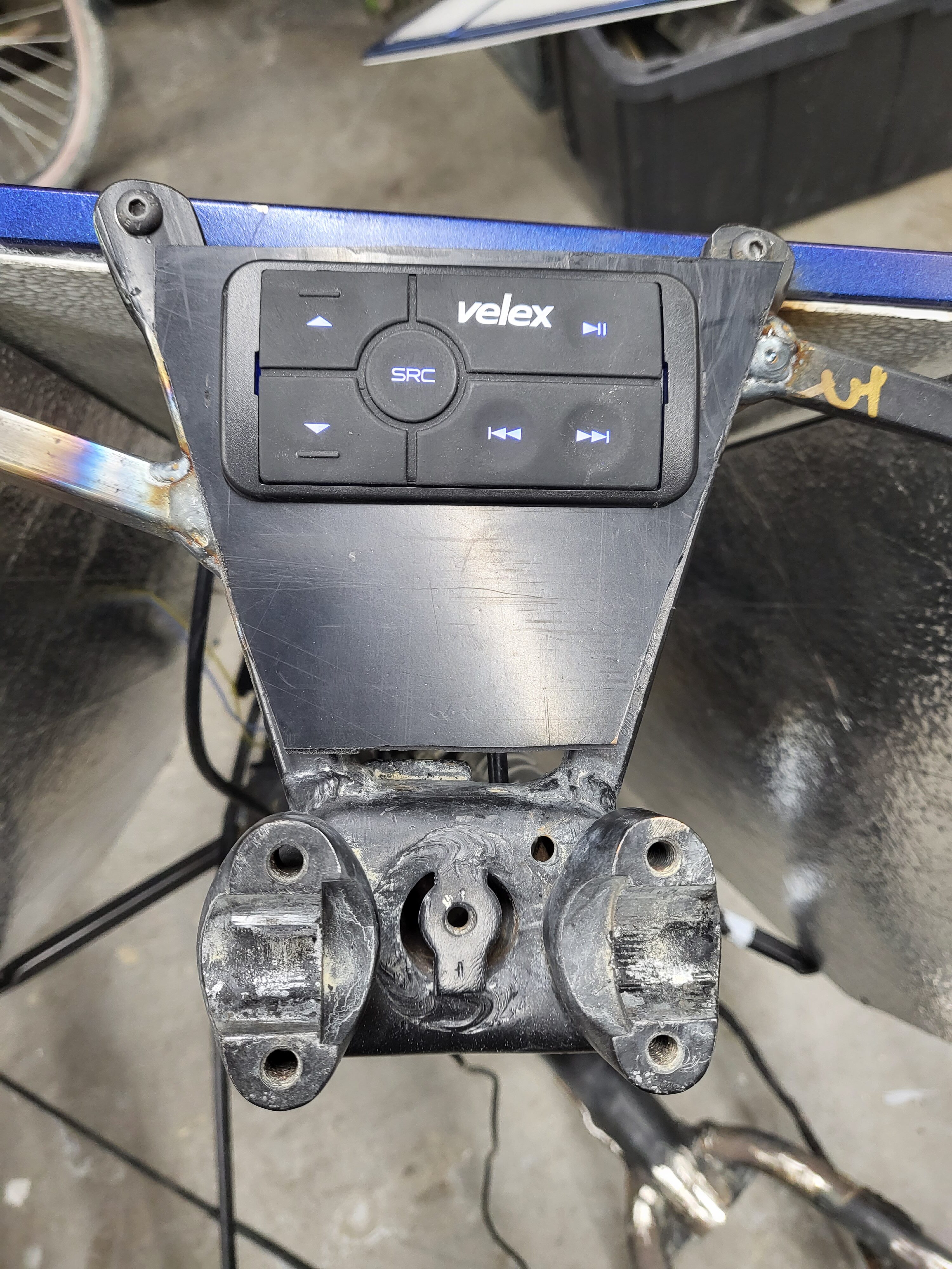
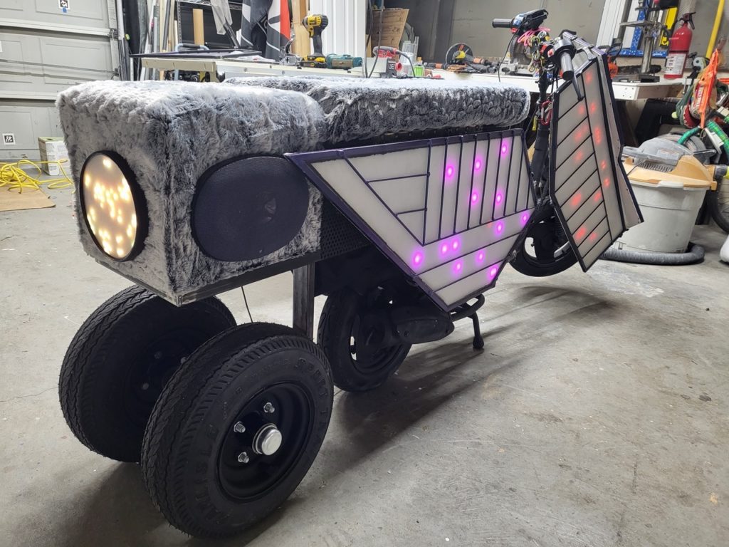
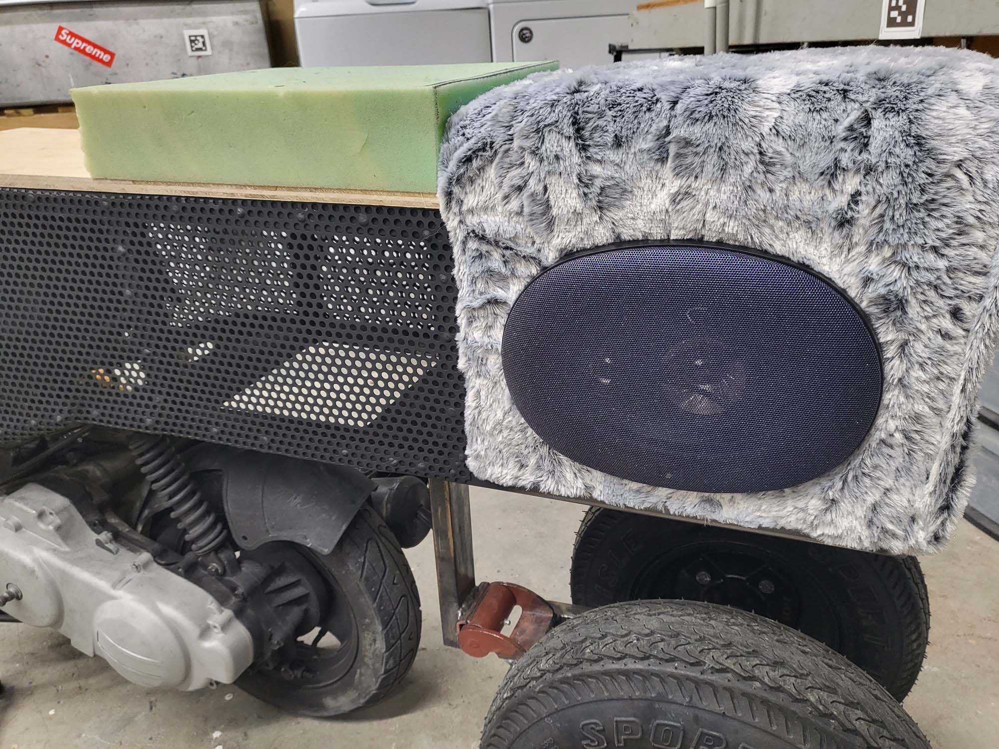
First off, I finished the audio system. The rear led panel and amp were mounted. The wiring has been completed and it is ready to be mounted once the frame is painted. I have been testing it out in the Texas sun and heat to make sure we don’t have any issues on the playa.
I am considering cutting an ABS plastic sheet to make a panel to cover the gap between the LED panels and the handlebars. This image is a POC of how the audio control remote will mount in said ABS panel.
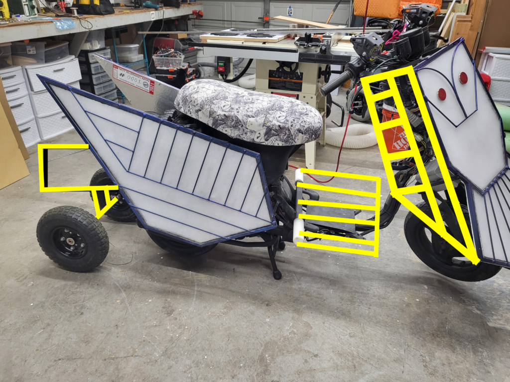
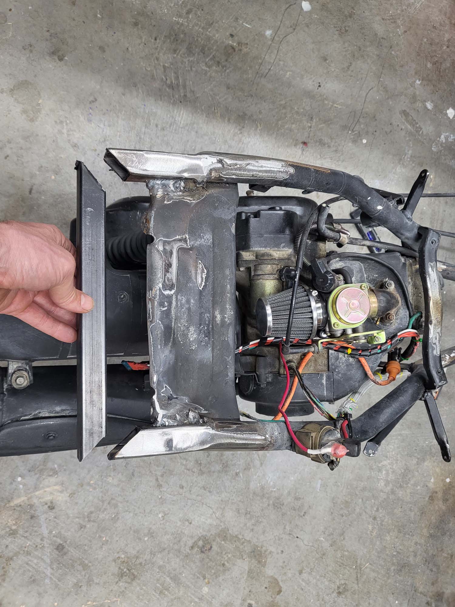
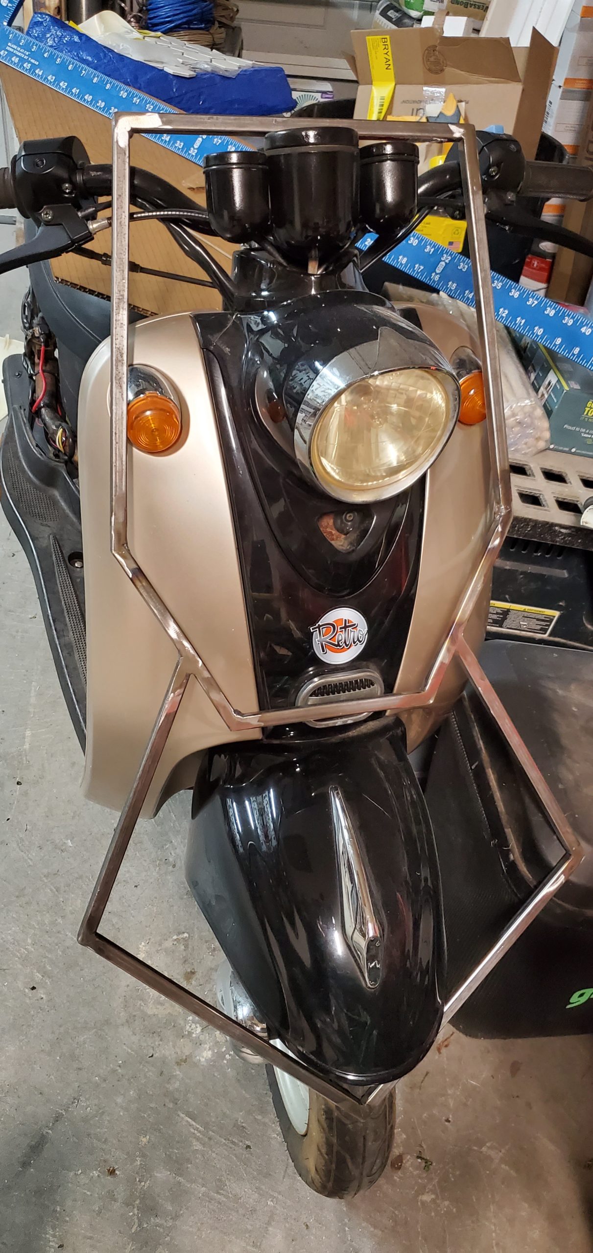
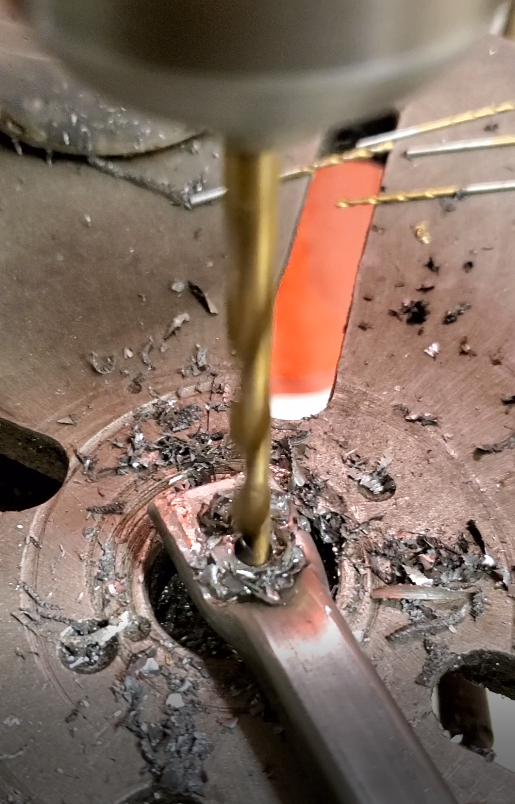
Next, I fabricated mounts for the new front panels and welded them to the forks. The mounts were made the same as the original panels, half-inch square steel tubes with one side flattened and a hole drilled into the flat side.
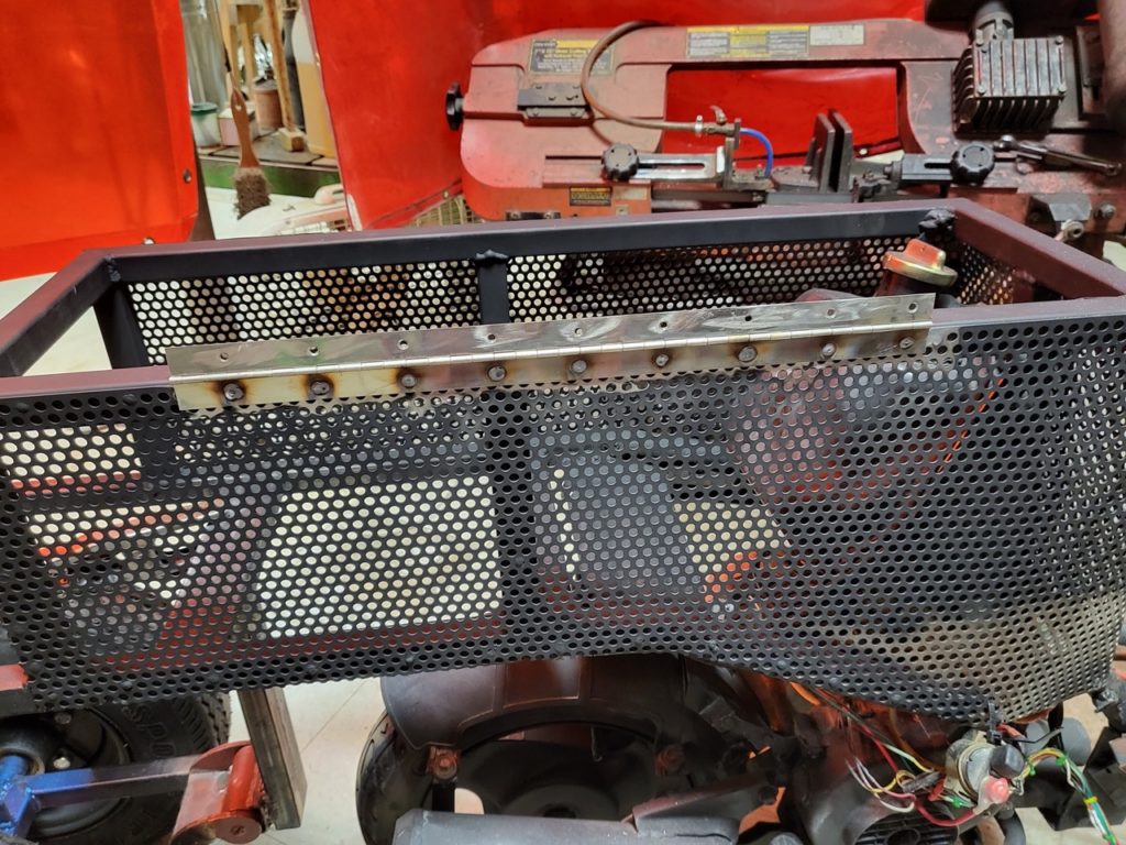
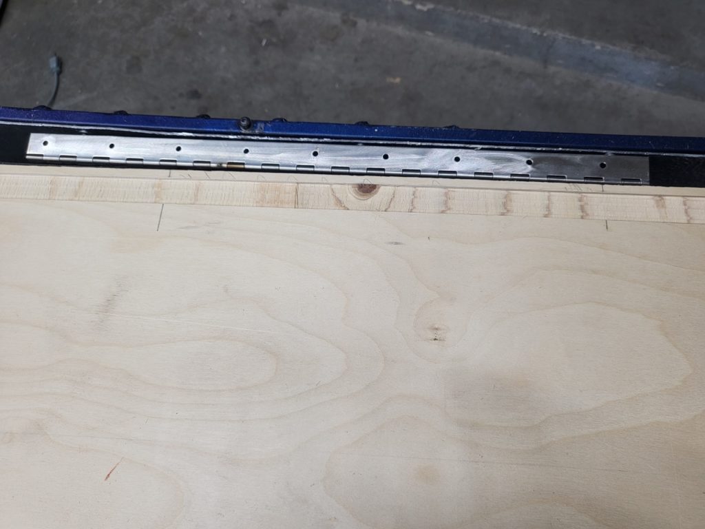
The same day I welded on the piano hinge that will allow the seat to flip up revealing the petrol tank, Li-ion packs, and storage. I used all my dado blades to make a wide dado in the bottom of the seat that the hinge will be recessed into. There is just enough space to let the seat open while bypassing the side LED panel.
Hinge welded to frameDado in bottom of seat
Speaking of the side panels… the mounts for these were mostly removed with the new frame so they needed to be re-welded. The side panels were originally mounted at an angle. I felt this gave the design more motion but this time I mounted them parallel with the seat to make it more comfortable for passengers.
This is close to the final design of version 2This is close to the final design of version 2
TODOs:
Weld driver footrest to frame Weld Passenger Foot Pegs Weld bottom to seat storage Remount Headlights Rework Rear Suspension Paint the whole frame Paint the motor Finish painting the wheels Finish cleaning up the wiring 3D Print Foot Rest Pad Build more Li-ion battery packs (recycled cells) Re-paint the original three pannels (maybe)
After a trip to the Playa in 2021 for Renegade Burn and discussing the vehicle with a couple of DMV volunteers, I knew I wanted to make some upgrades. Before that could start, I needed to give it a good cleaning and look for any issues.
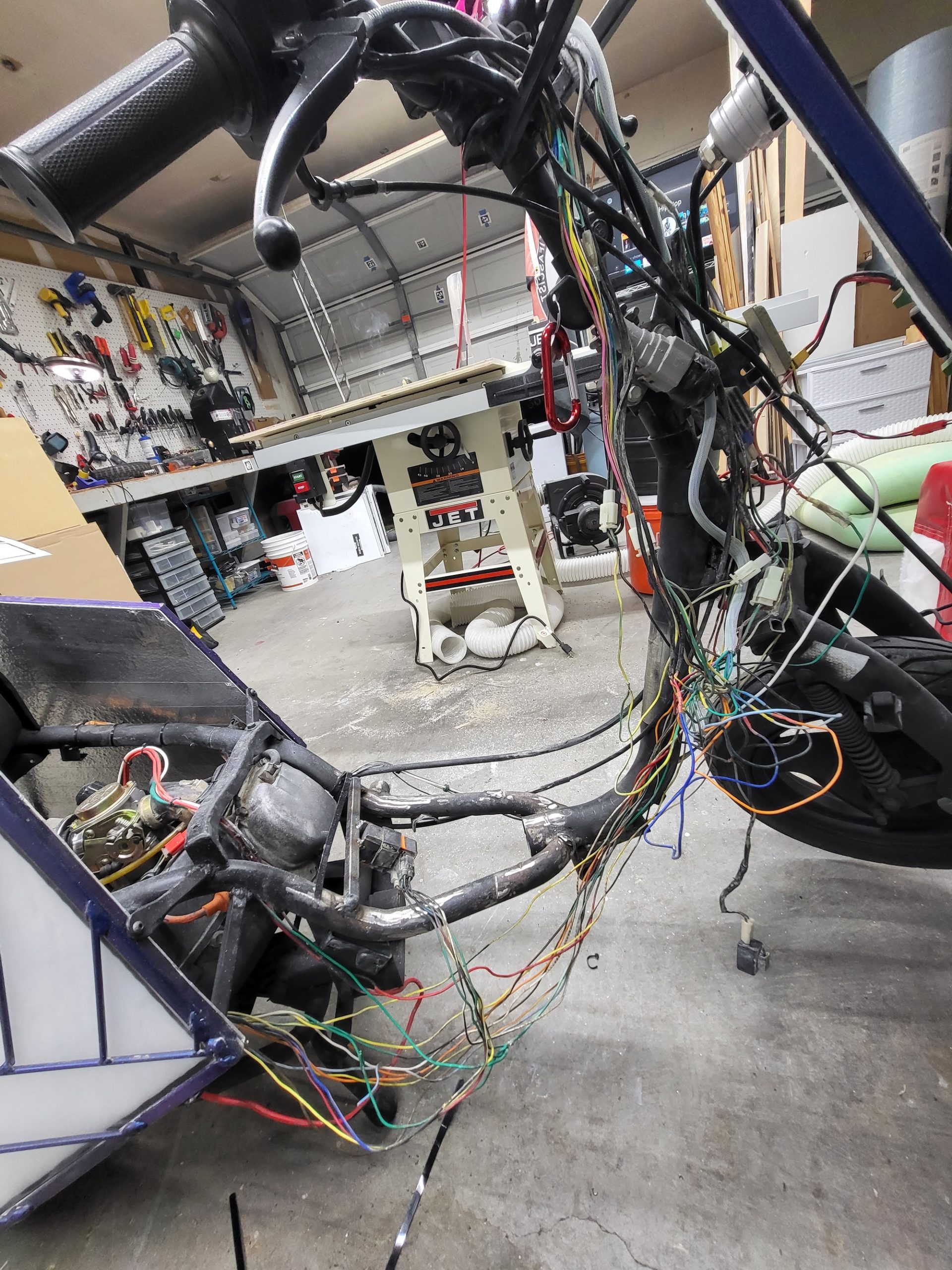
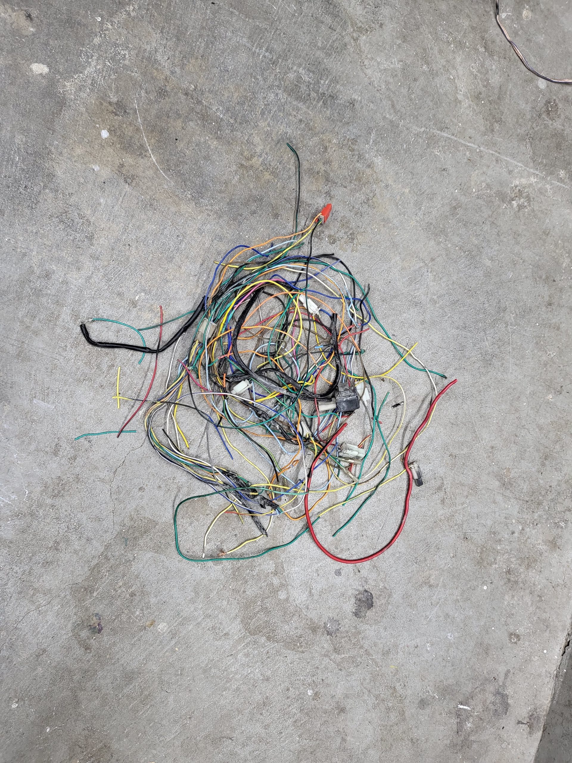
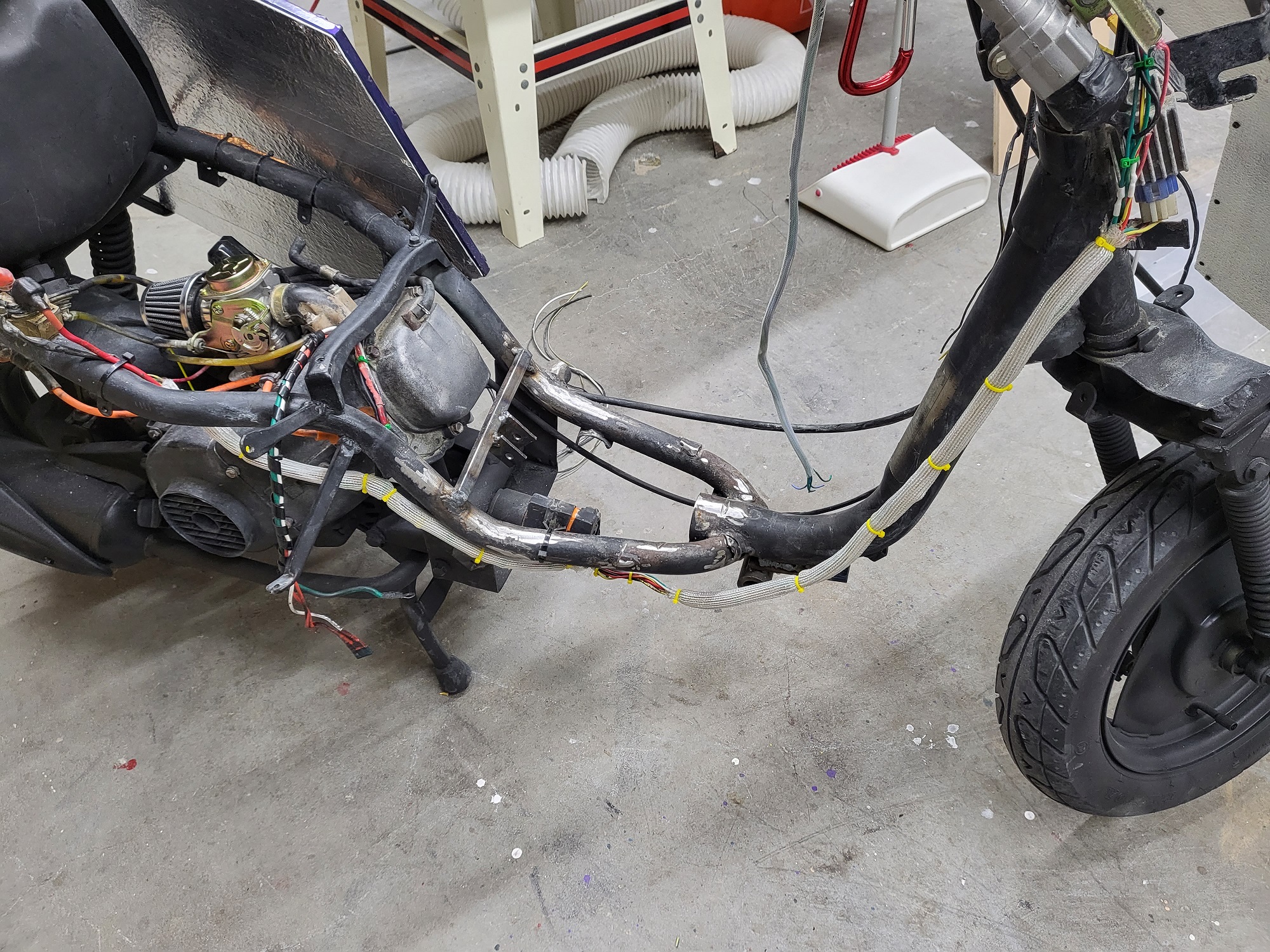
The first thing I wanted to clean up was the wiring. It was something I really neglected and it was pretty much a rat’s nest zip-tied together. I redid all the solder joints because the OEM’s work was very sloppy. This isn’t over, but it is a great start. I also removed anything that was not required to make it functional and street legal.
Original MessWhat Was RemovedCurrent
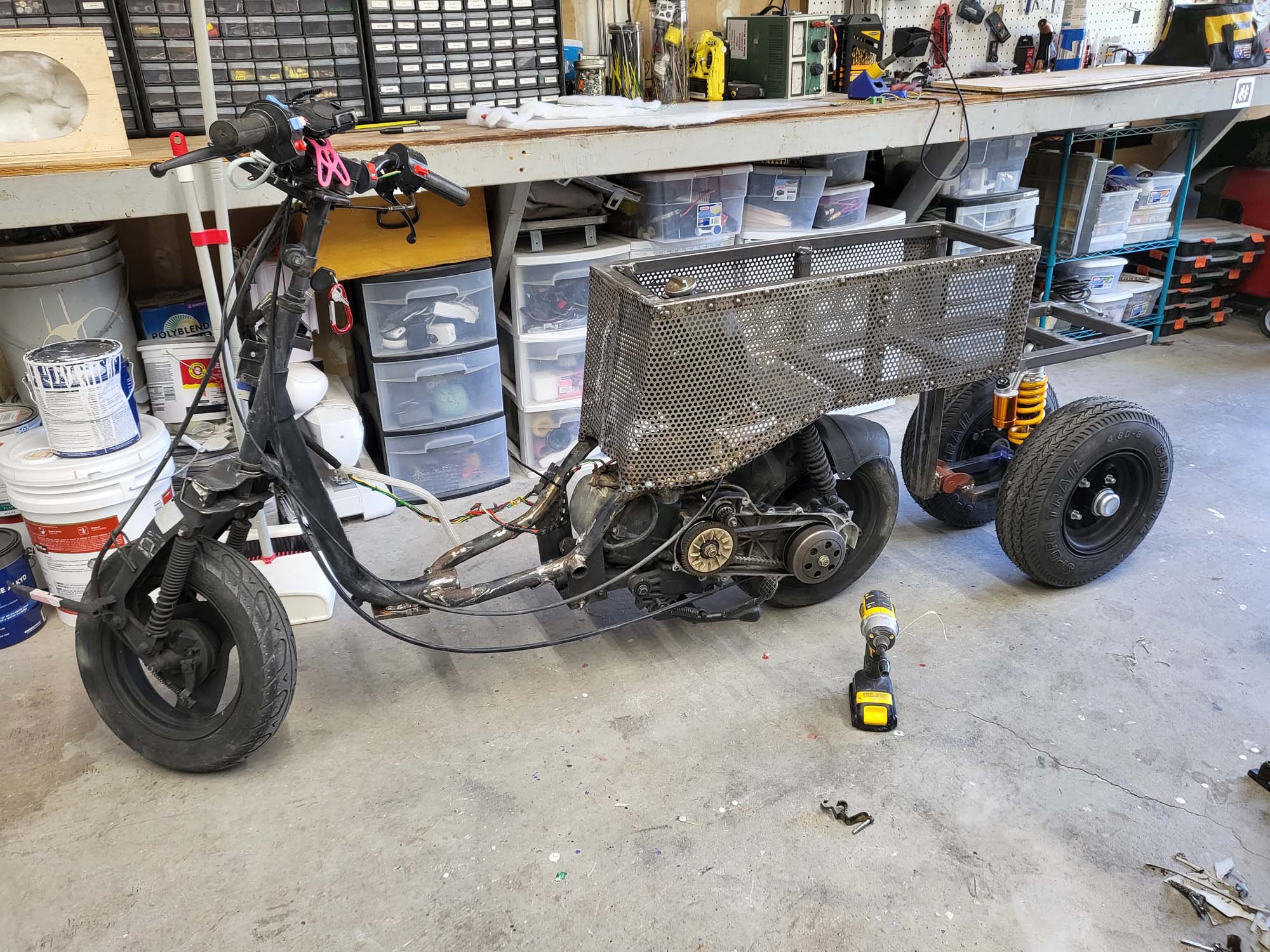
The plan is to extend the back and seat so that more people can fit comfortably. Under the back will be two 12 inch trailer wheels roughly a foot apart that keep the vehicle upright. I will have to build some type of suspension for it. I also need to build a panel for either side of the front forks. This is to hide the base vehicle more while looking at it from the side. I also want to build a better platform for the driver’s feet.
Rough Idea of What I Am Going For
After cleaning up the wires, the next step was to build two more LED panels, one for either side of the front forks. I am starting to be able to knock these out fairly fast now.
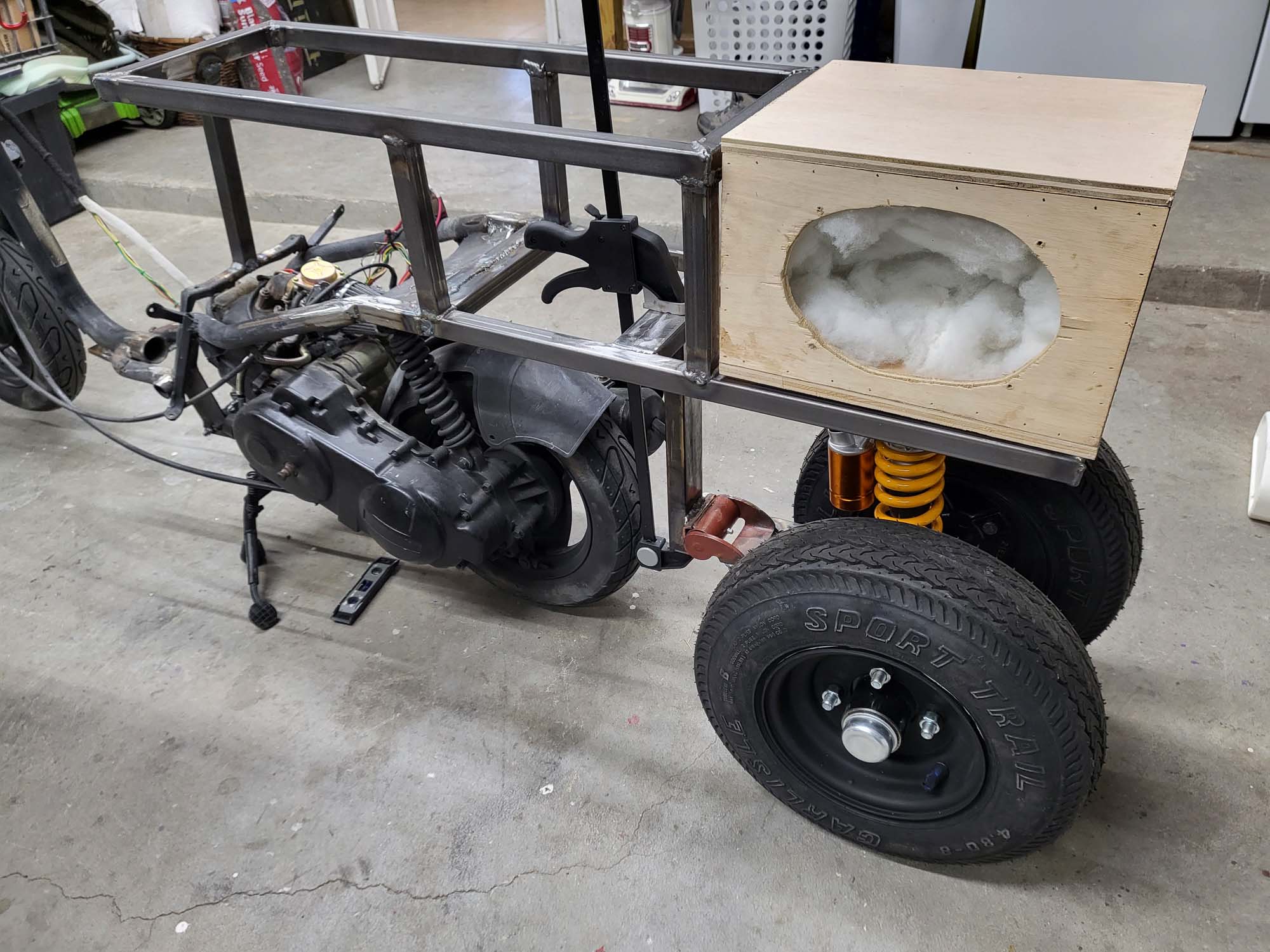
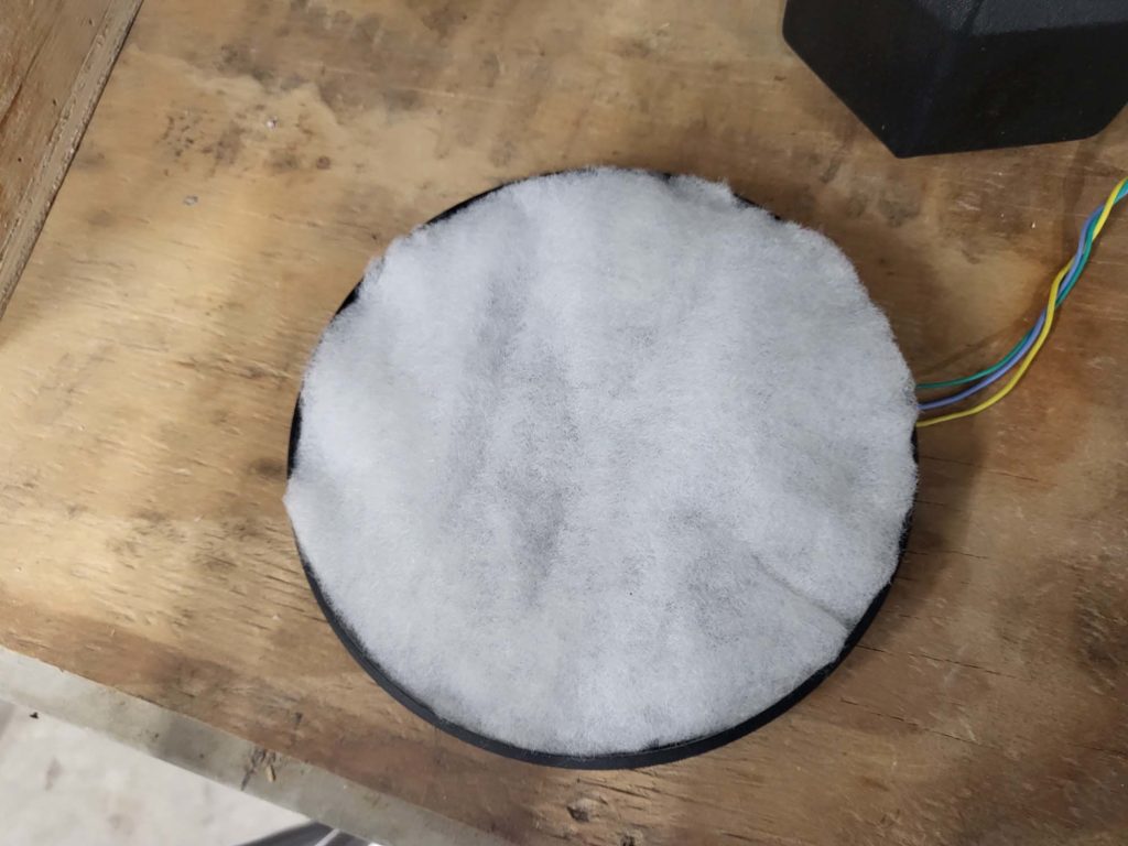
Here is a perfect example of how much better it looks with the Polyfil.
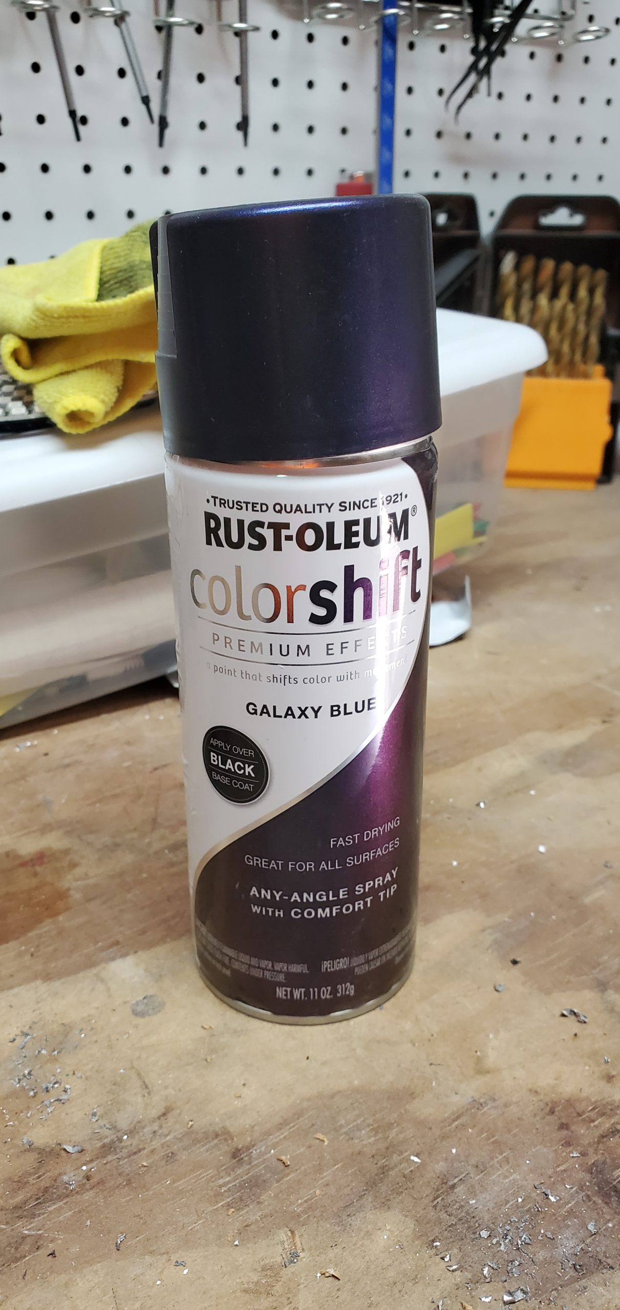
The color shift paint I was initially using was something I had on my shelf. After we decided to use it, I had a hard time finding it because the company discontinued it. When I did find a store that had it in stock, it was ridiculously expensive. I was experimenting with mica pigments for a separate epoxy project, and realized I could make it myself. I am using Eye Candy mica powders–a 5:1 mixture of their Geisha Doll and Sapporo.
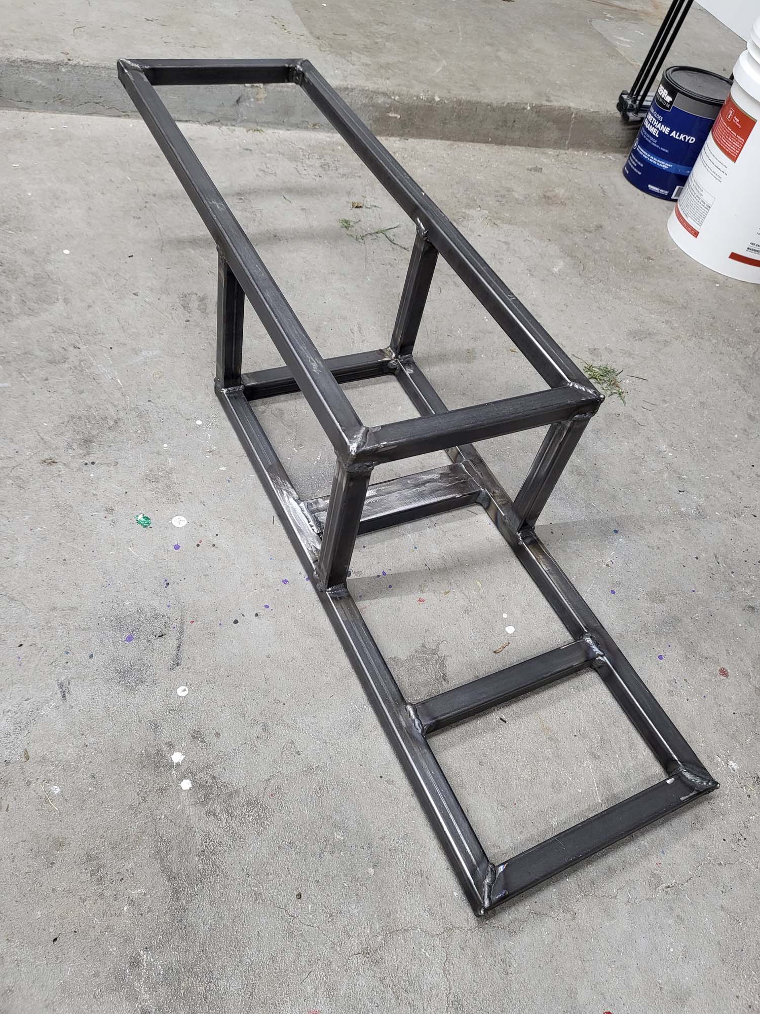
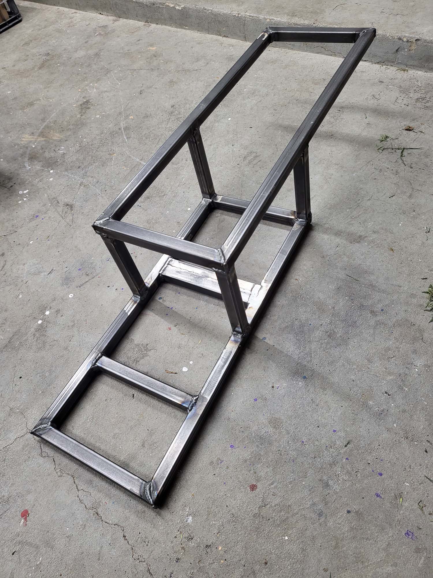
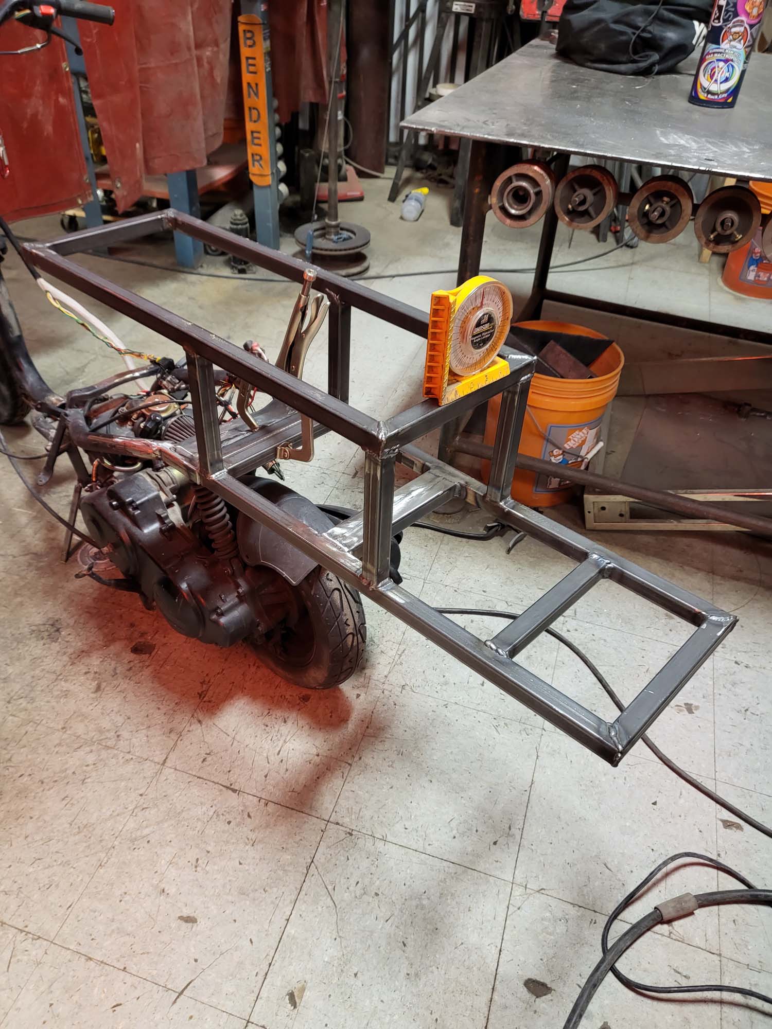
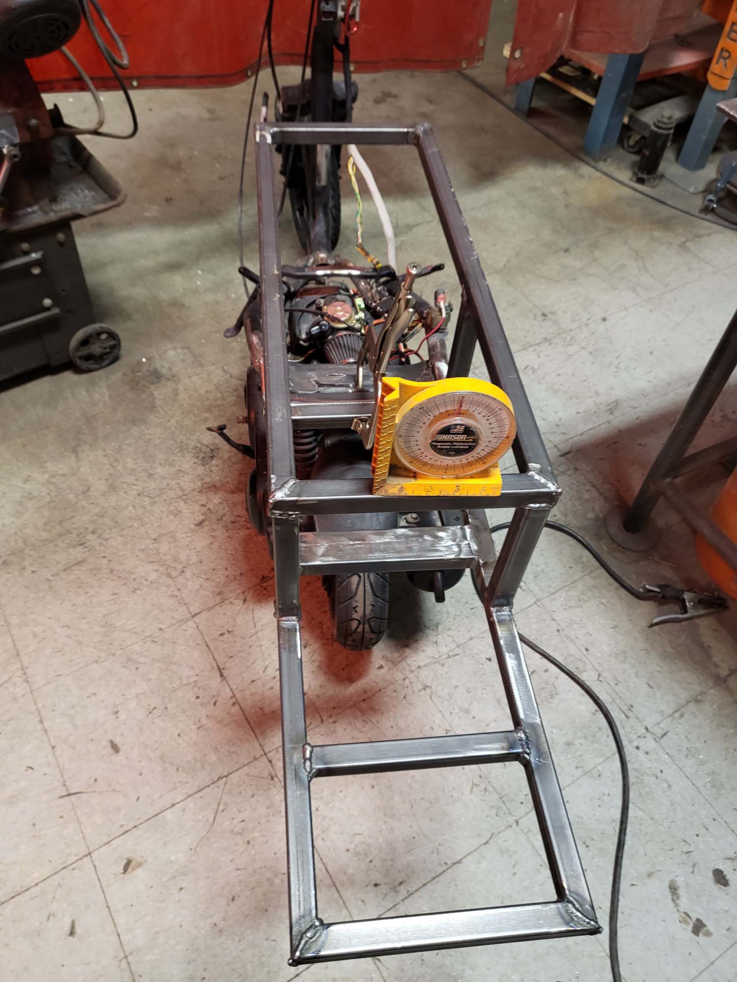
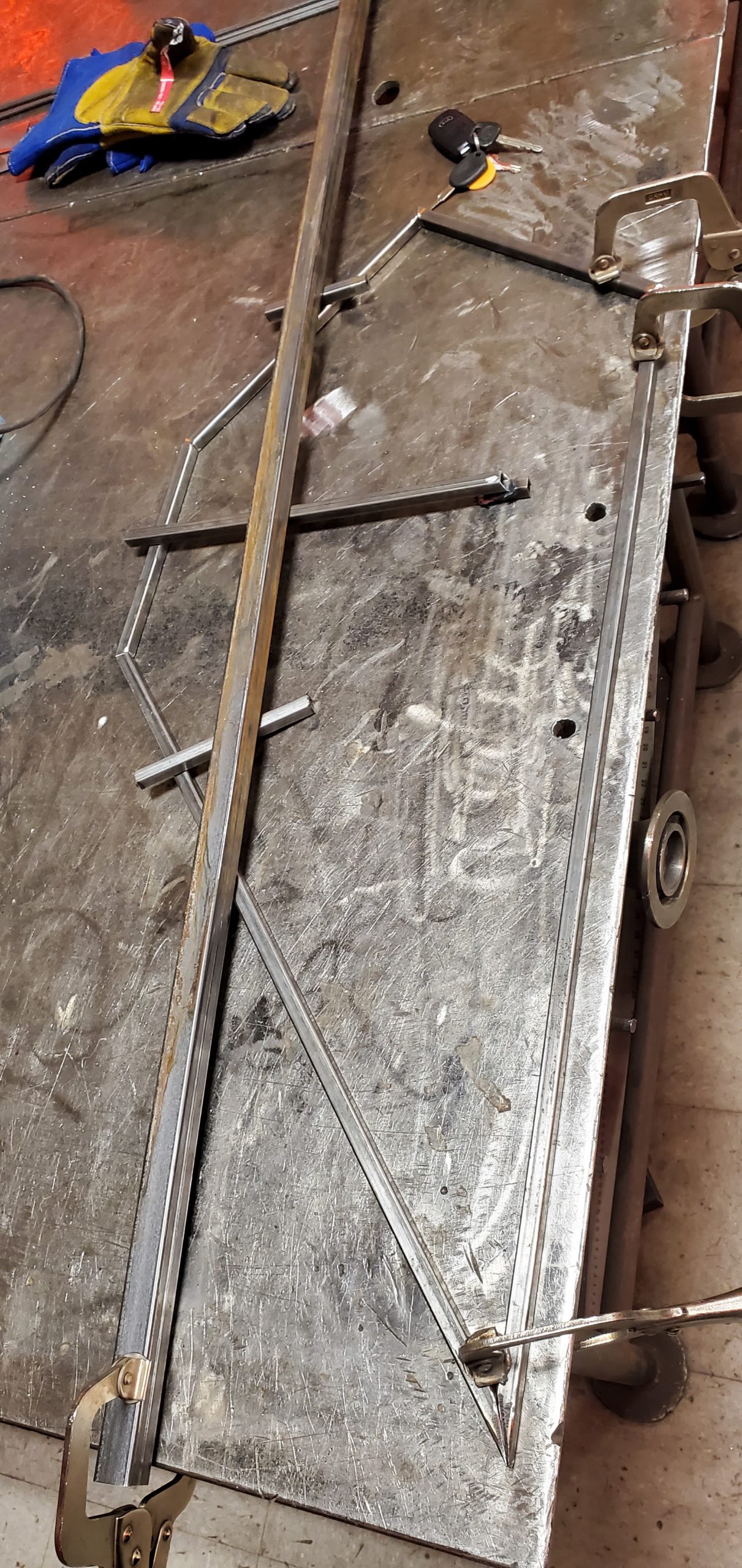
After the panels were done, I started to rebuild the frame. I used one-inch square tubing for the new sections of the frame. The first step was to remove as much of the frame as possible and weld a piece of one-inch square tubing to the frame to give myself a good mounting point.
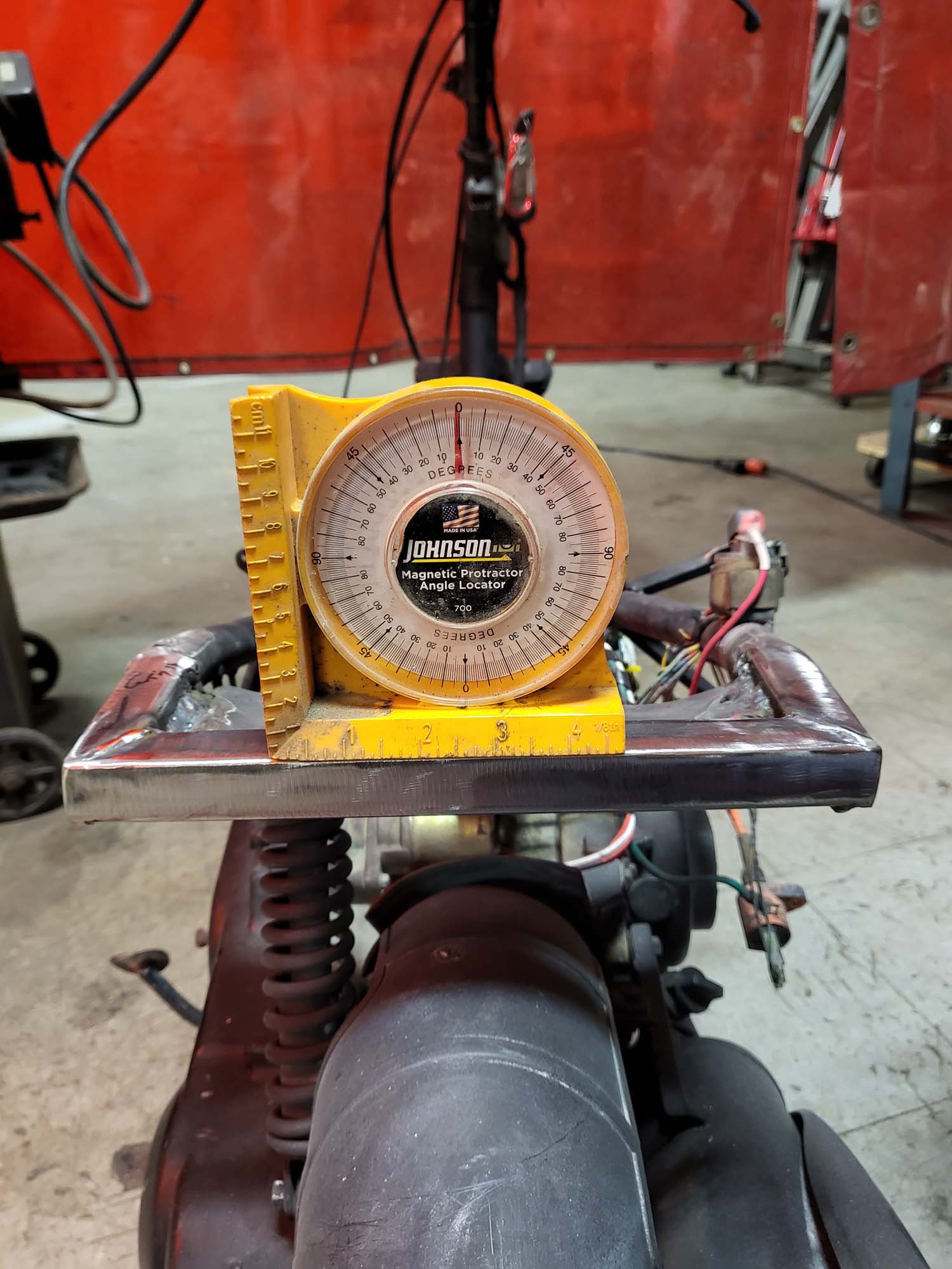
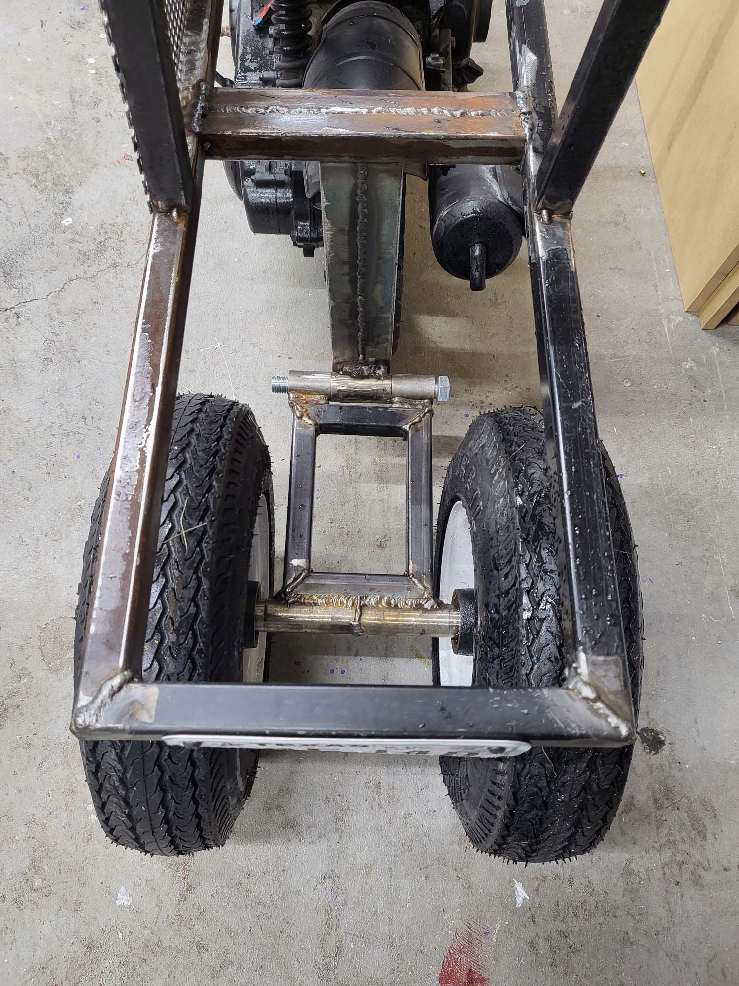
I built the new section of the frame off the bike so I could make everything as square and parallel as possible. Doubled up the tubing where the new section mounts to the old frame and for the rear suspension.
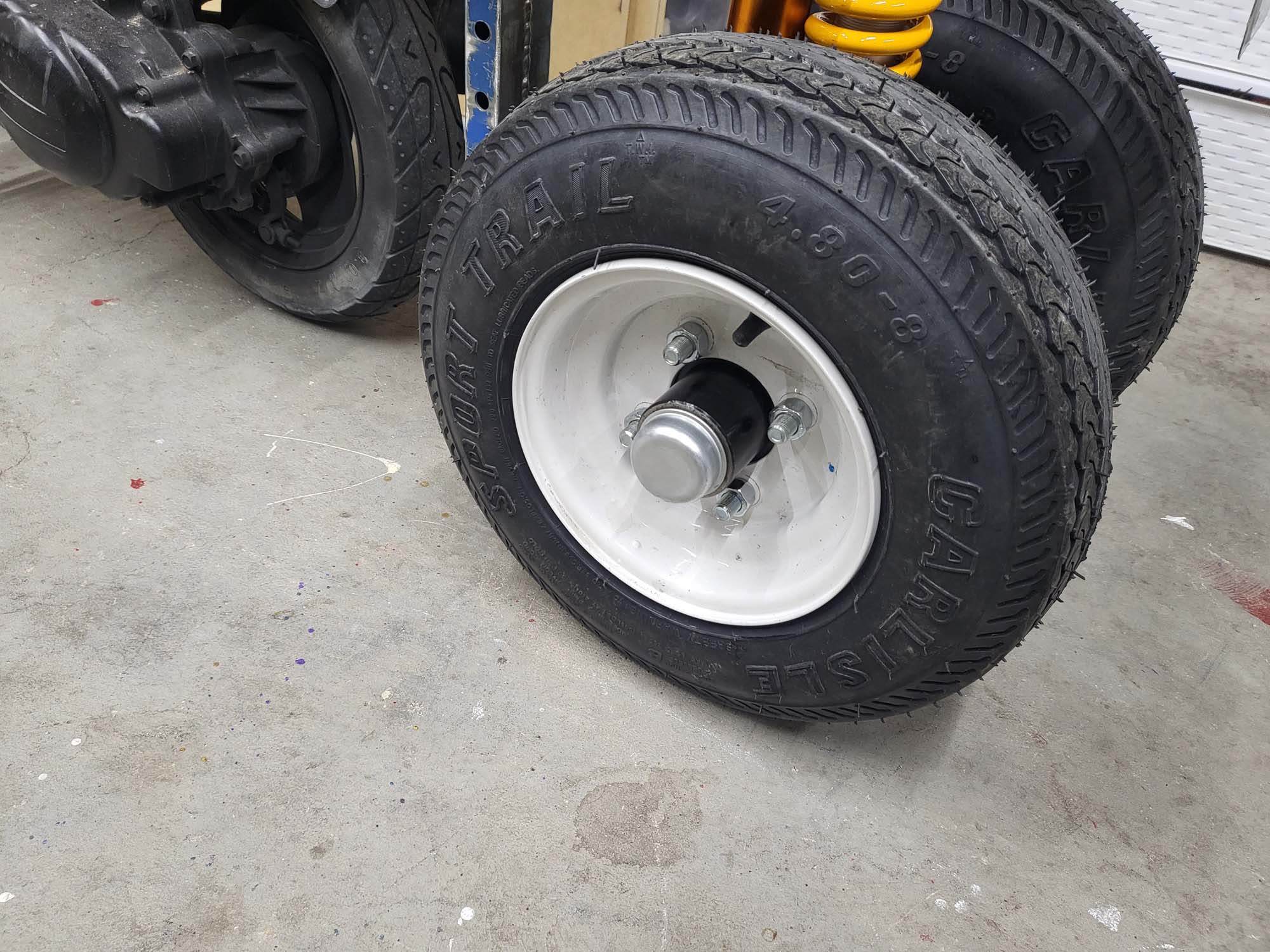
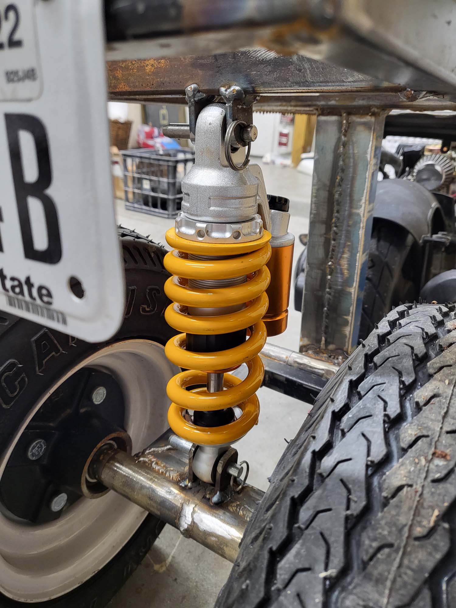
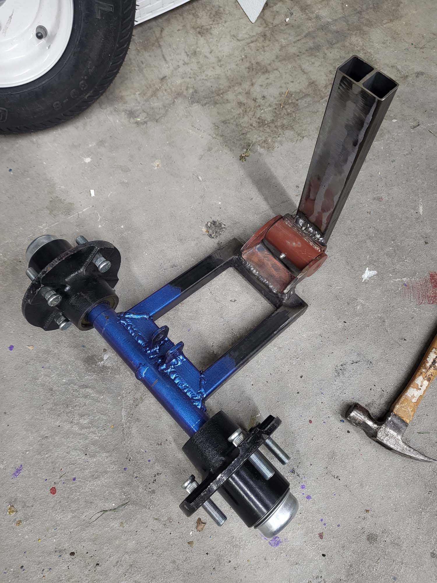
I had to design suspension for the two trailer wheels on the back. This was something new to me and I went through a few iterations. I asked a some experts what they thought… Some suggested a swing arm and others said to mount it rigid but slightly off the ground. I went with the swing arm idea.
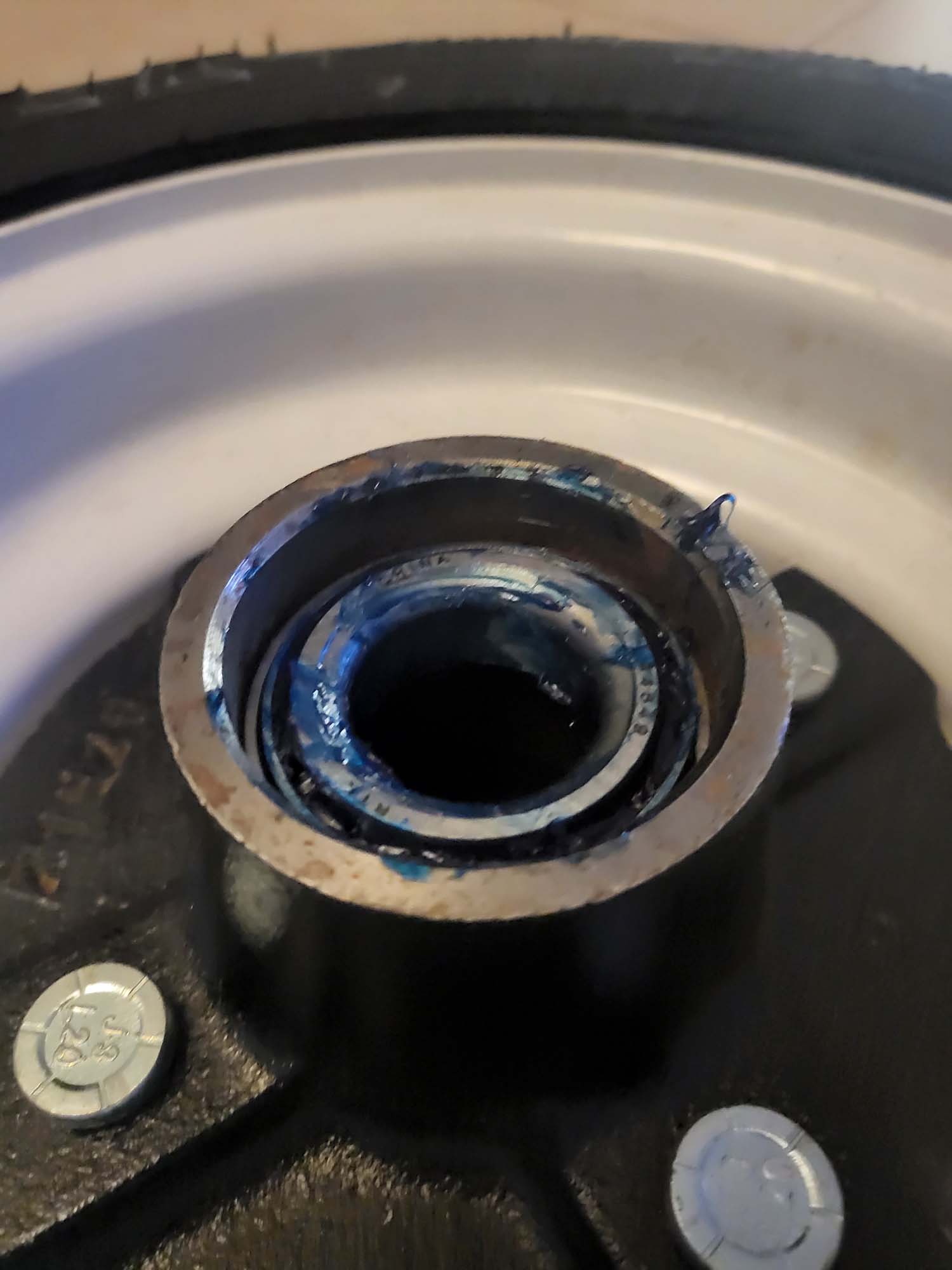
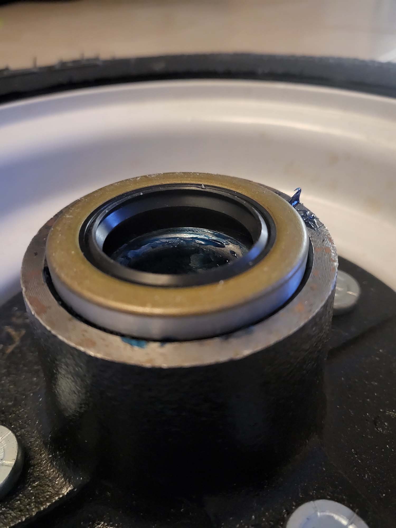
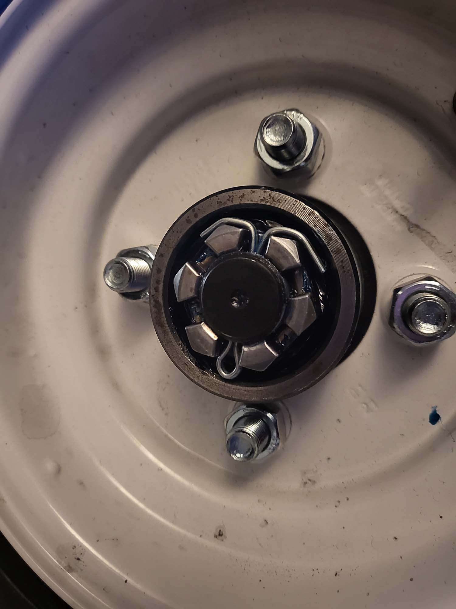
I ordered trailer hubs kits from Trail Parts USA. They were worth every penny and saved me so much time on the lathe. I tried a couple of different hedges. Honestly, I may come back to this because the current hinge has too much slop but I want to finish up the rest of the current tasks.
Original MeasurementsGreasing Up The BearingHub SealCrown NutHub CapAssembled1st HindgeThis Shock Is Too Stiff2nd Hindge
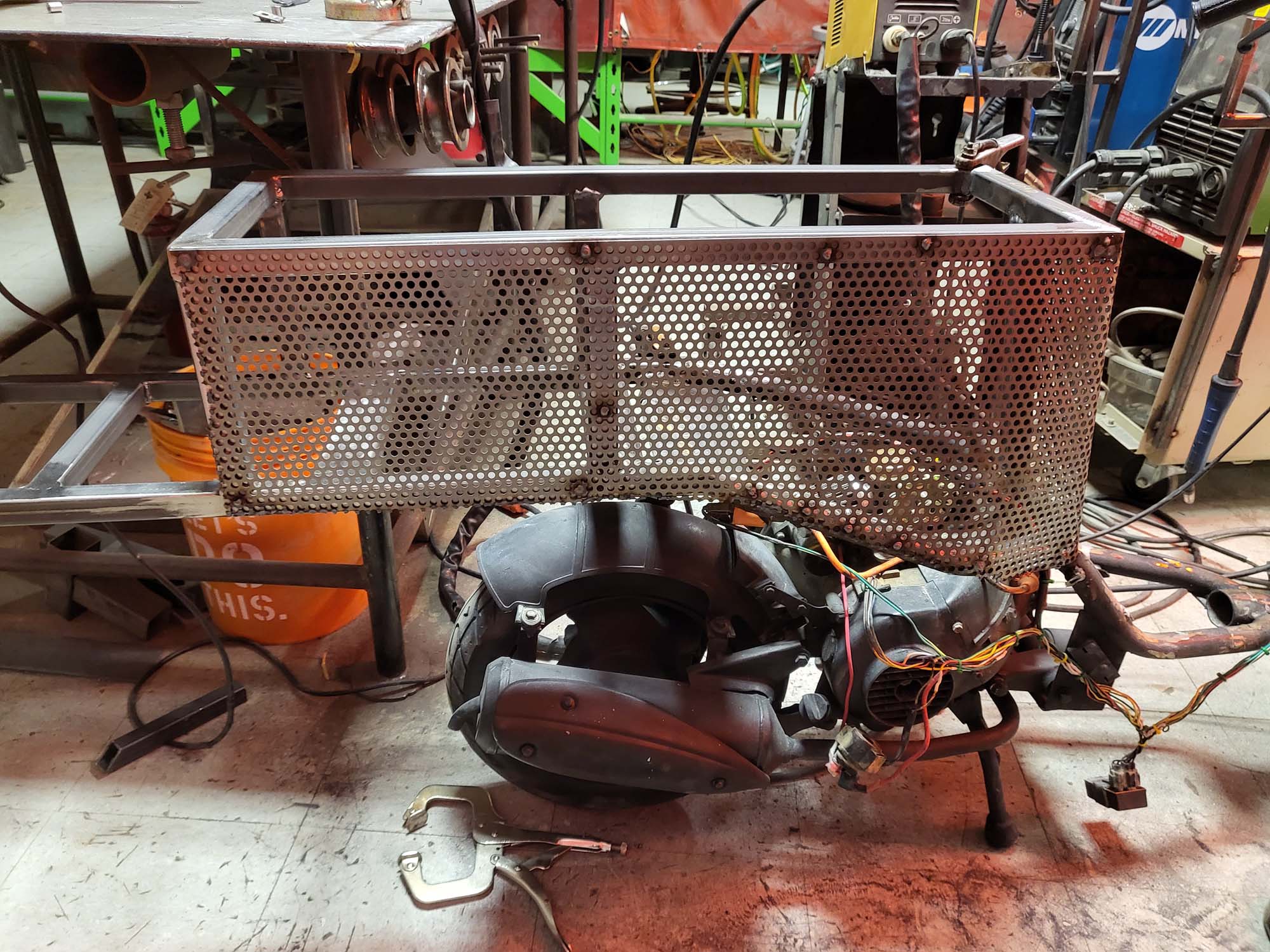
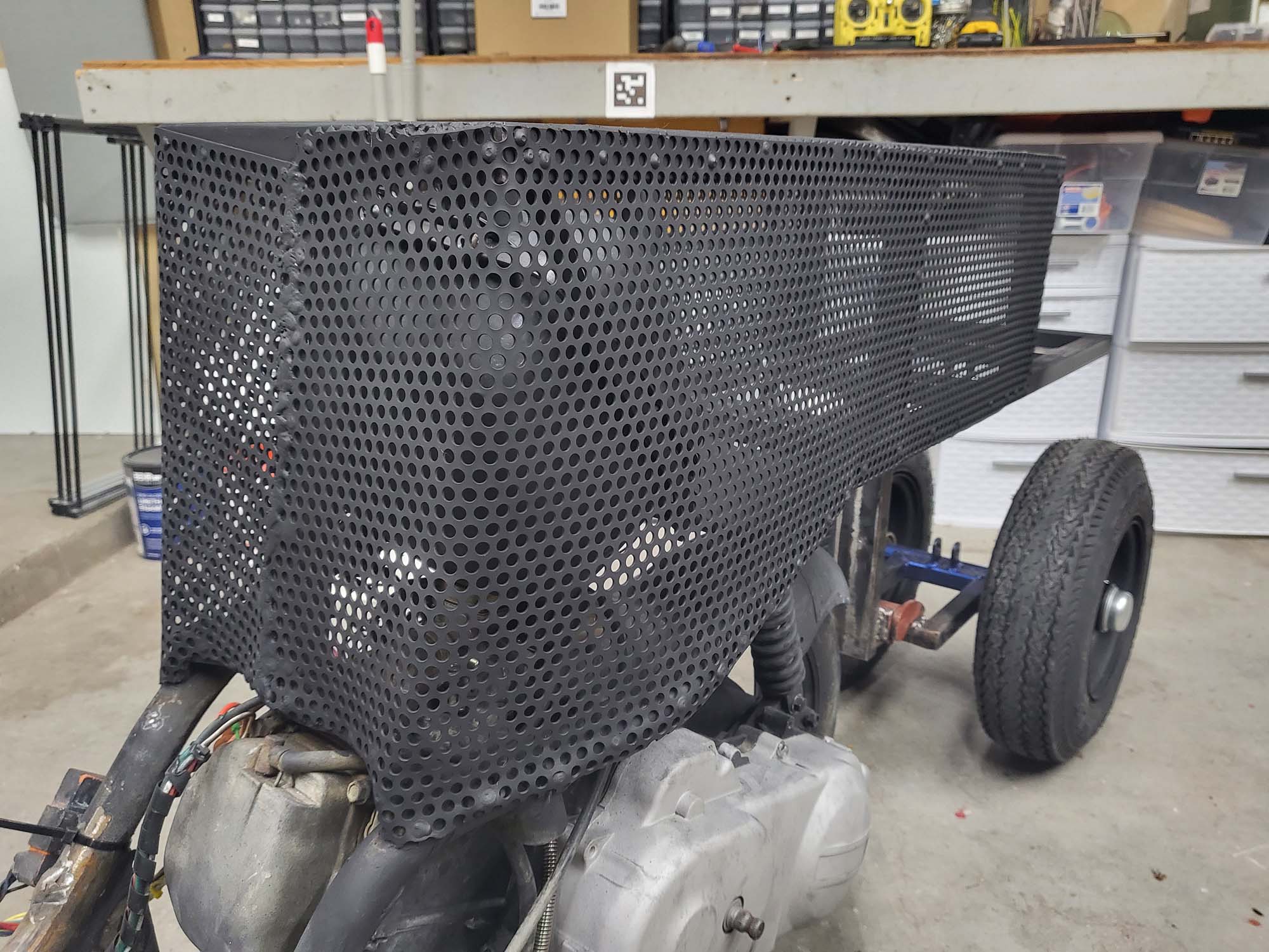
Now that everything is framed I wanted to enclose it to create storage in the seat. My work gave me a few sheets of this steel with holes in them. I still have to add the bottom pieces… that is in my to-do list below.
One Side DoneBoth Sides DoneBase Paint
The sound system in version 1 consisted of a bunch of cheap junk I picked up from Goodwill. They did not sound that bad but I wanted something that fit ascetically with the design. I am using marine grade equipment due to the corrosive nature of the Playa dust. There is a 3-way 6×9 on either side of Hootie. These are powered by a 300-watt Velex Powersport Class D Amplifier.
Built The BoxGlueing Foam & Fux FurFoam Makes It A SeatI’m Gonna Fix The Top Left CornerAll Sparkle No Pony
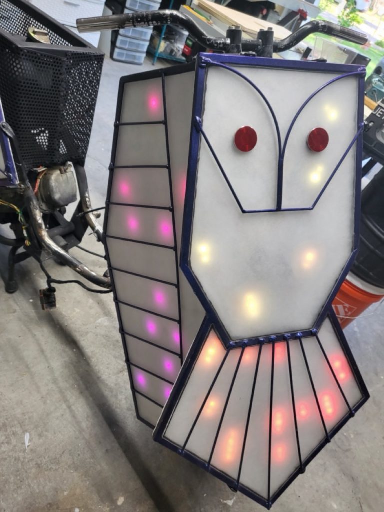
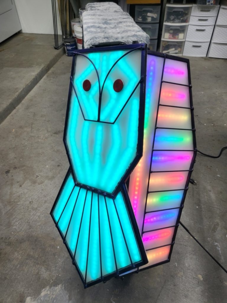
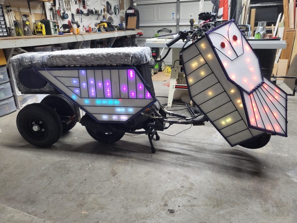
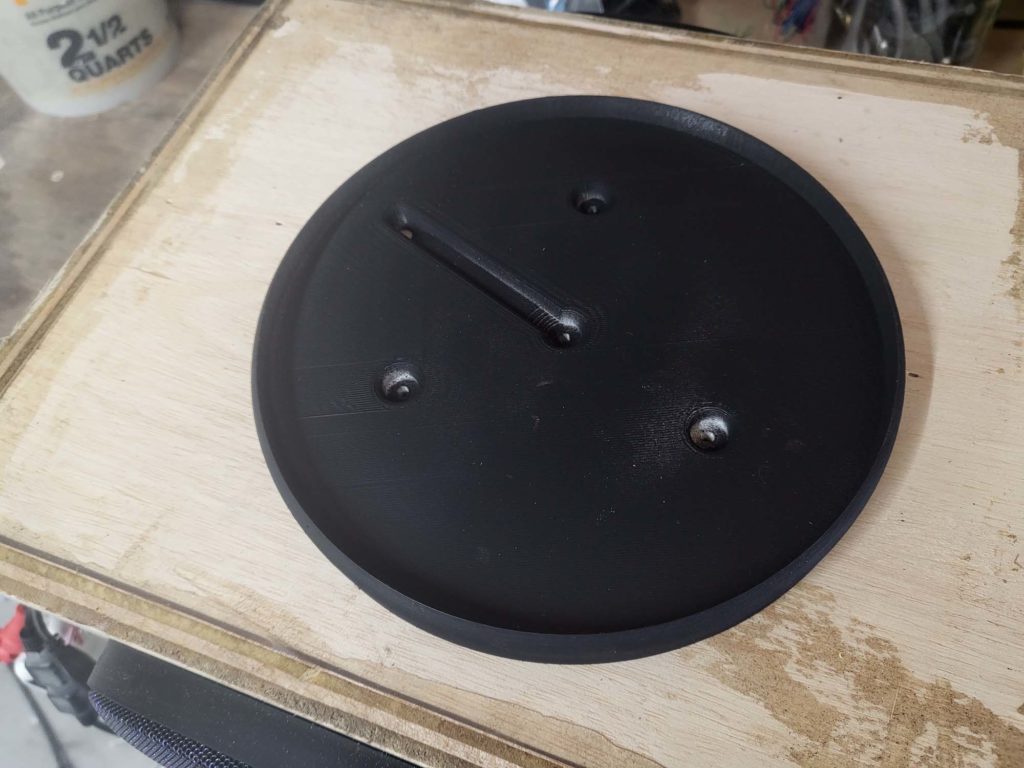
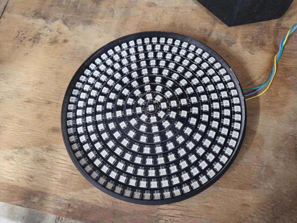
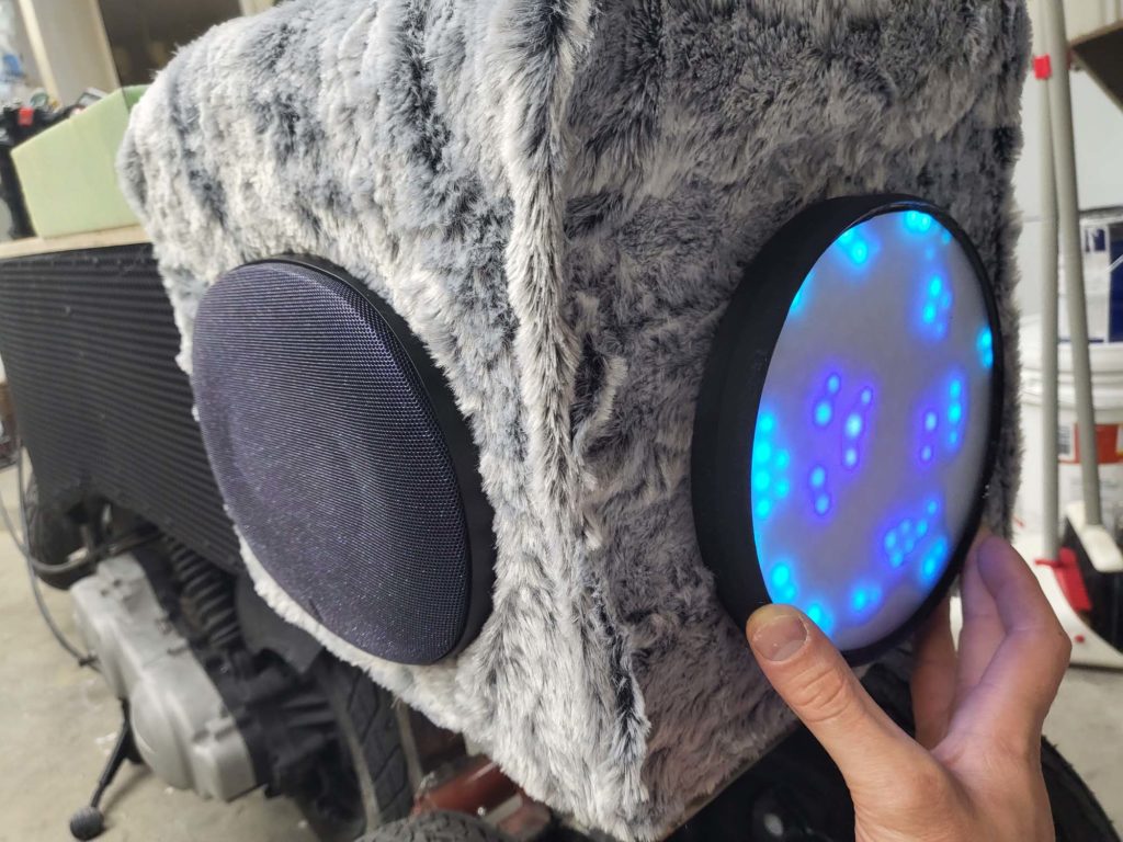
Hootie V2 has just over 1,200 individually addressable LEDs. Each side of the vehicle has a minimum of 240 LEDs. The back LED panel doubles as a brake light. When the vehicle’s brake engages, all 241 LEDs instantly turn red. The front of the vehicle has headlights with high and low beams.
Painted The 3D Print241 LED RingGot To Have The PolyLaser Cut AcrylicSanded FrostedOptocoupler Isolation Siliconed In PlaceGonna Go Here
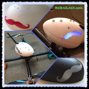
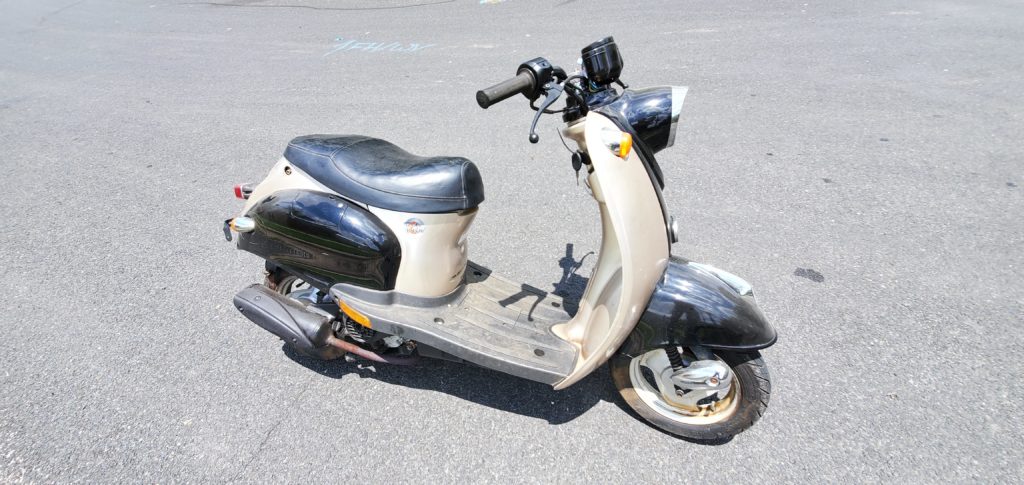
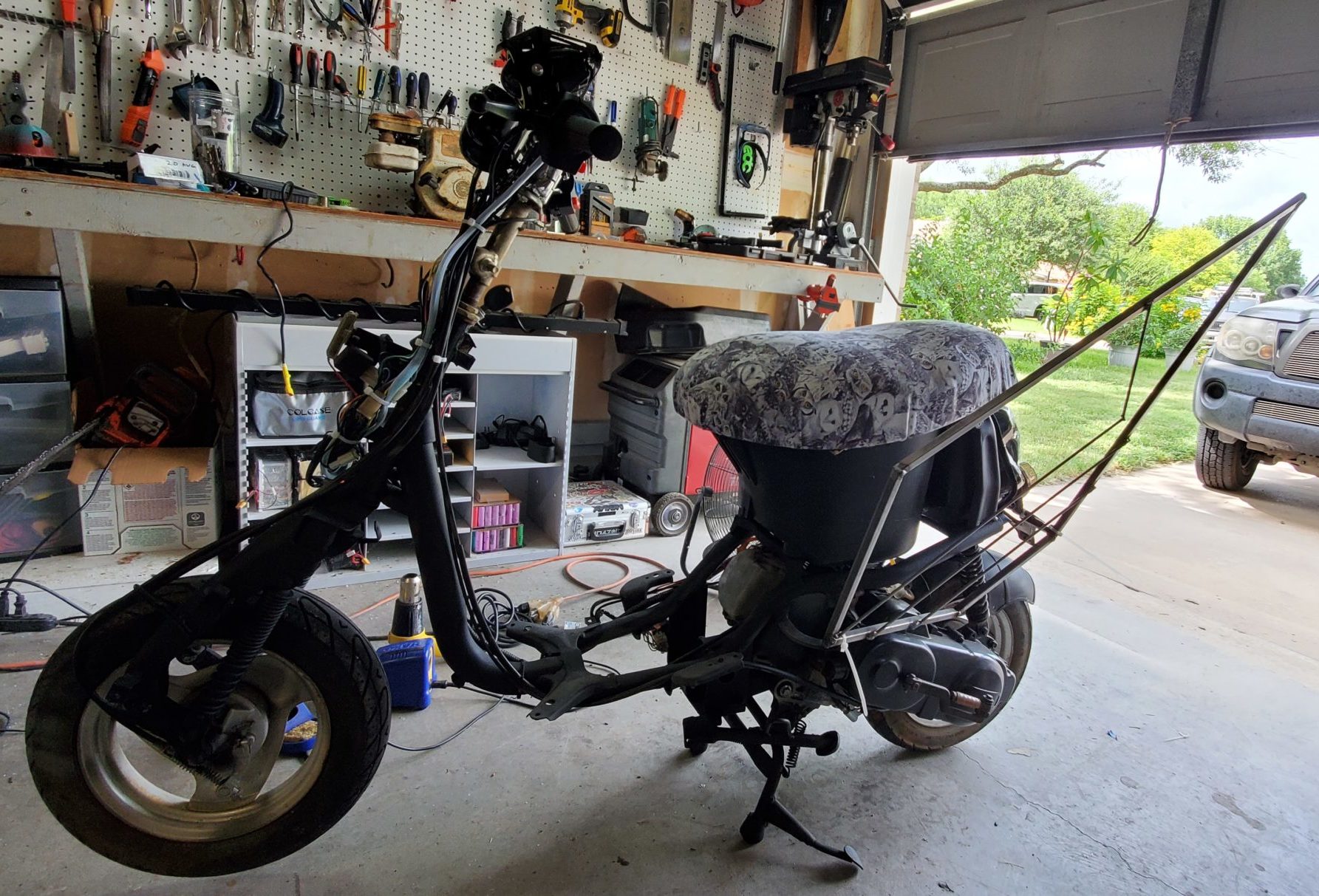
The base of the vehicle is from a 50cc Retro scooter. I purchased the scooter in May of 2021 not knowing what I was going to do with it, but within days, the Hootie project began. This mutant vehicle project brings in all my skills as an artist, maker, and fabricator, including coding, welding, metal lathe, laser cutters, 3D printing, CNC, electronics, and more.
The Orginal Vehicle
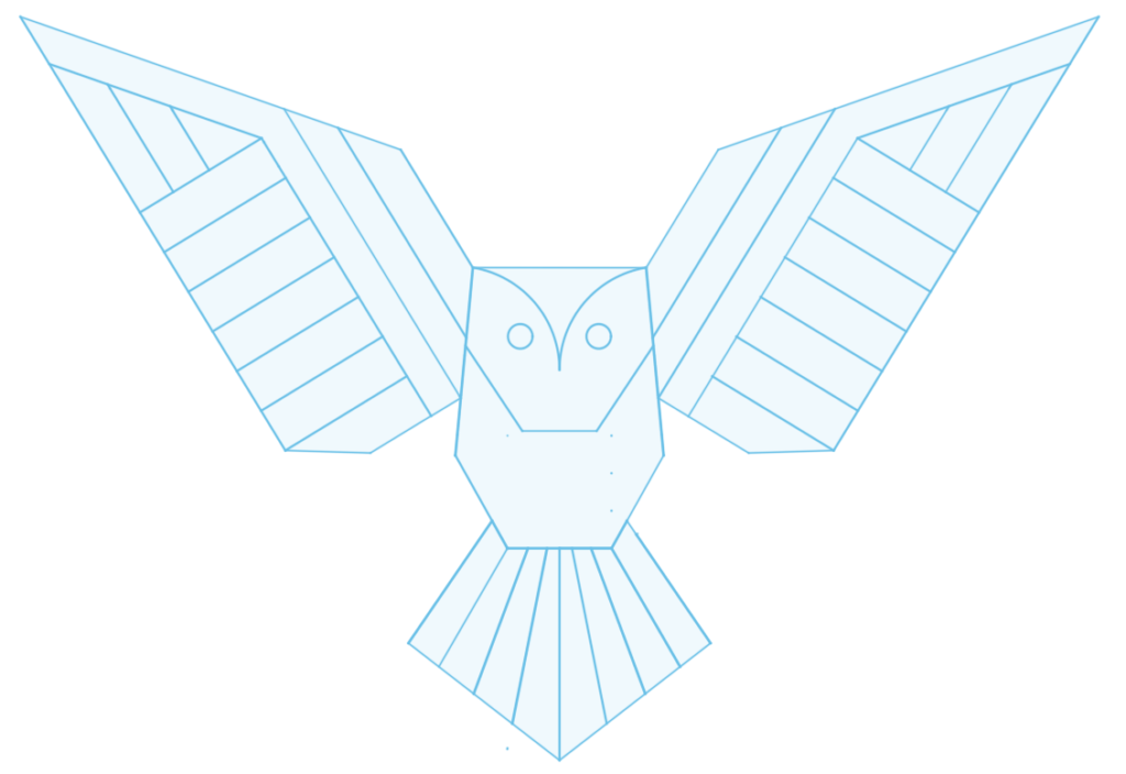
I knew I wanted to build an owl, I did some research. I looked for other owl mutant vehicles, different kinds of owls, drawings of owls, opinions from my partner, to name a few sources of inspiration.
I knew I wanted the aesthetic pieces of the vehicle to be removable panels. This was mainly for ease of transportation (1,800 miles each way). Once I had a direction of where I wanted to go, I did a 2D sketch in Fusion 360 using the dimensions of the scooter’s frame. The idea was to have the center body on the front of the scooter and have a wing on either side hiding the motor.
1st Drawing
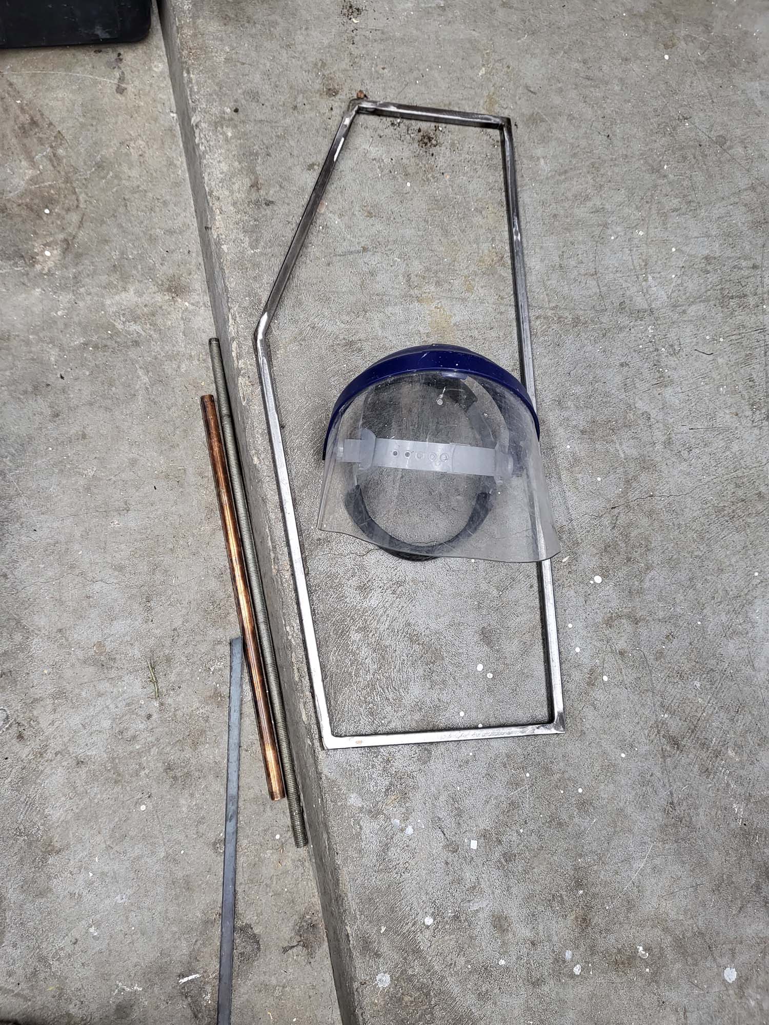
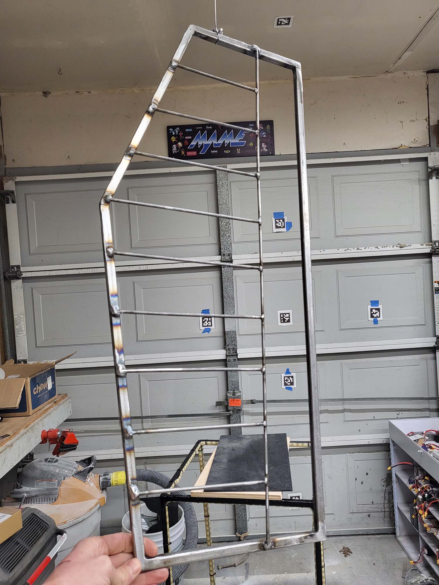
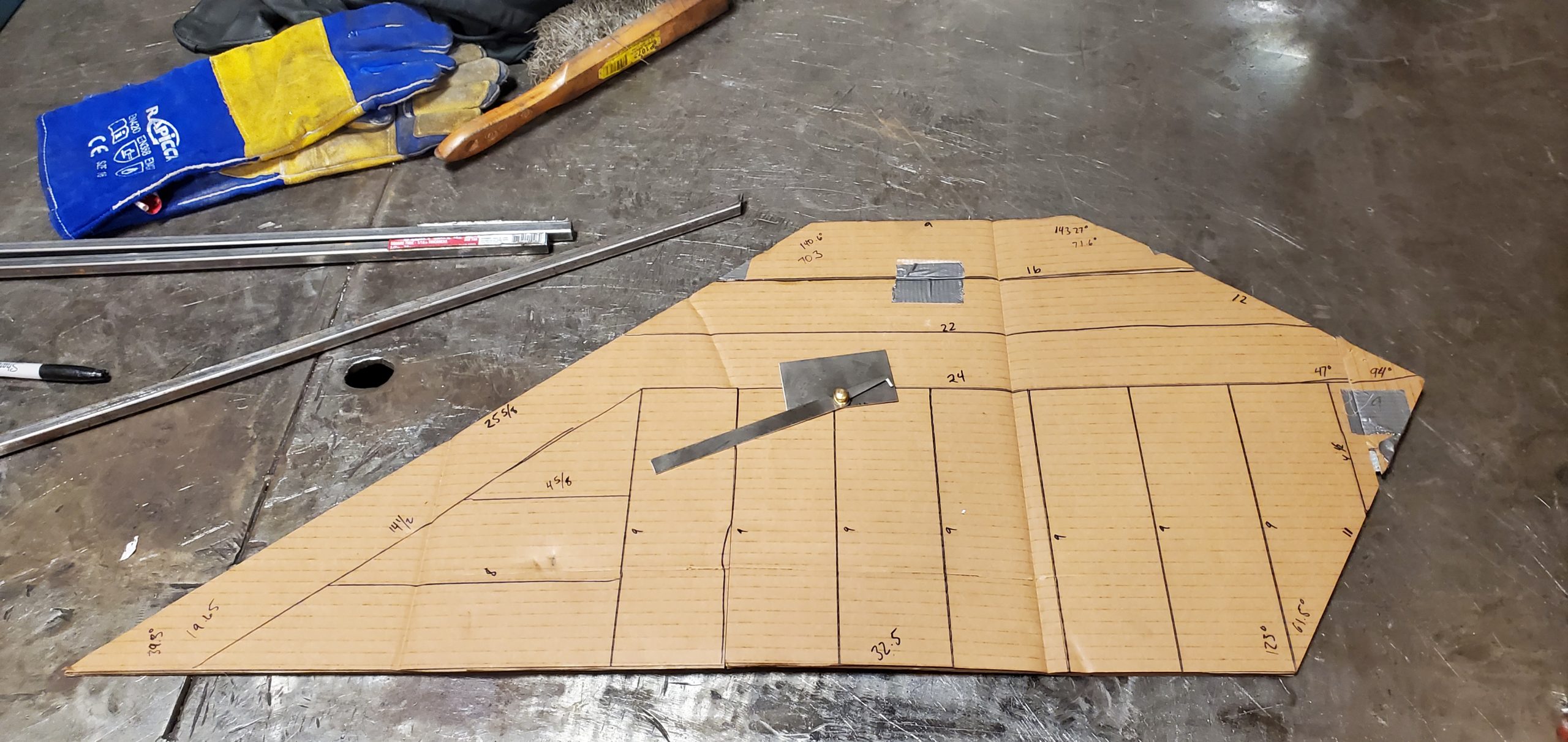
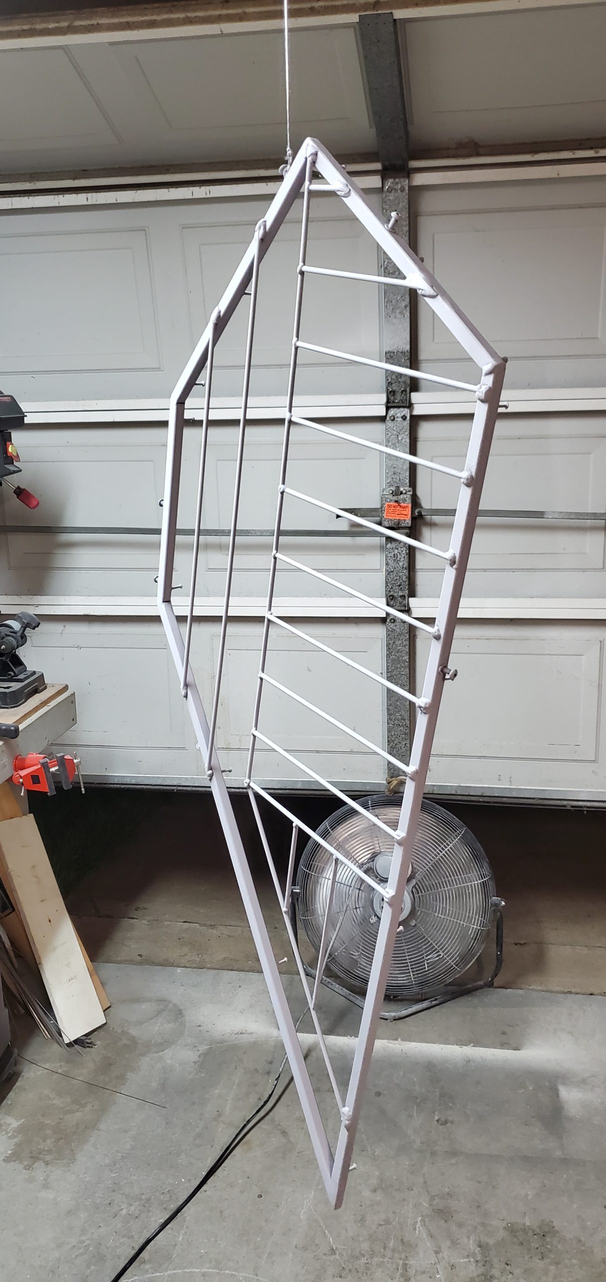
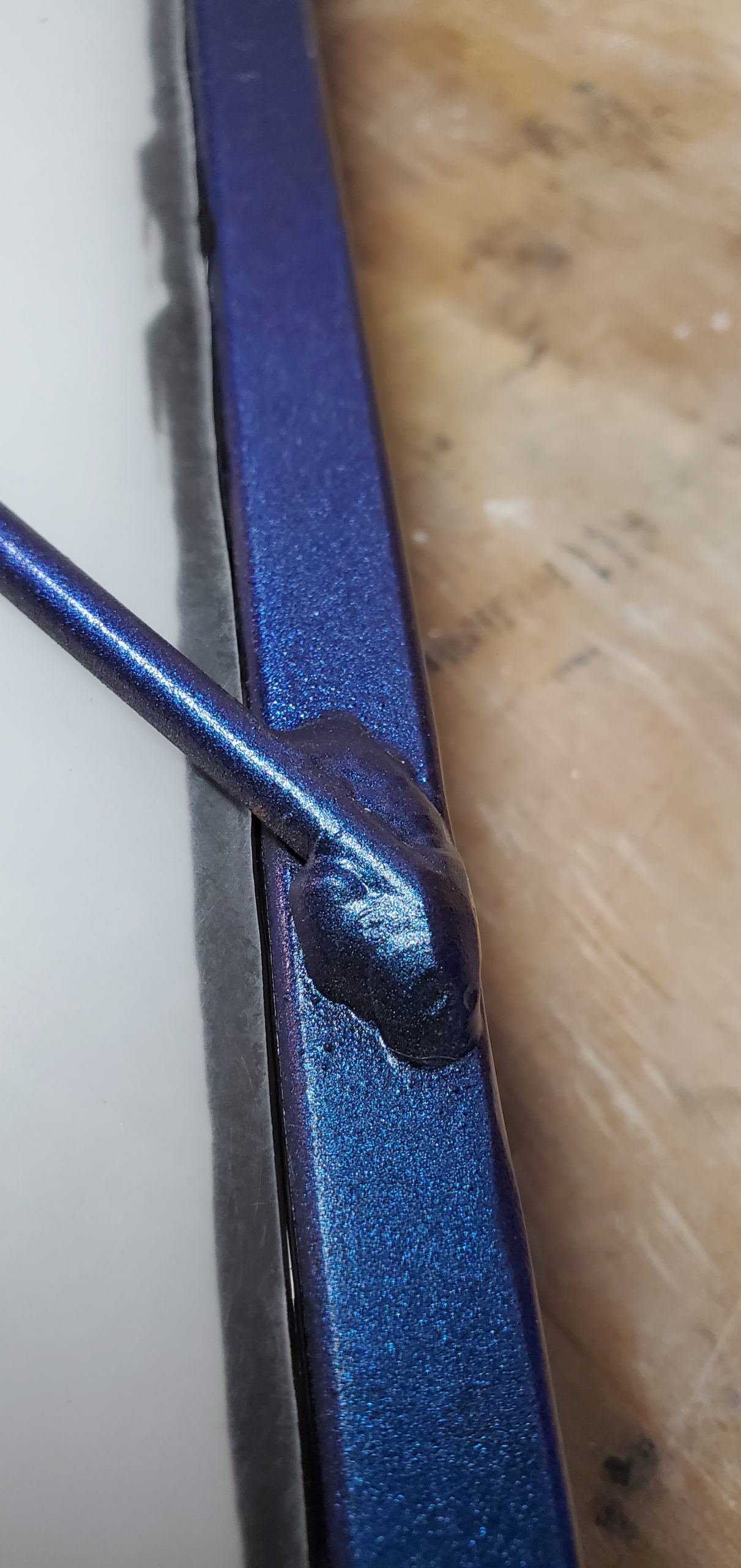
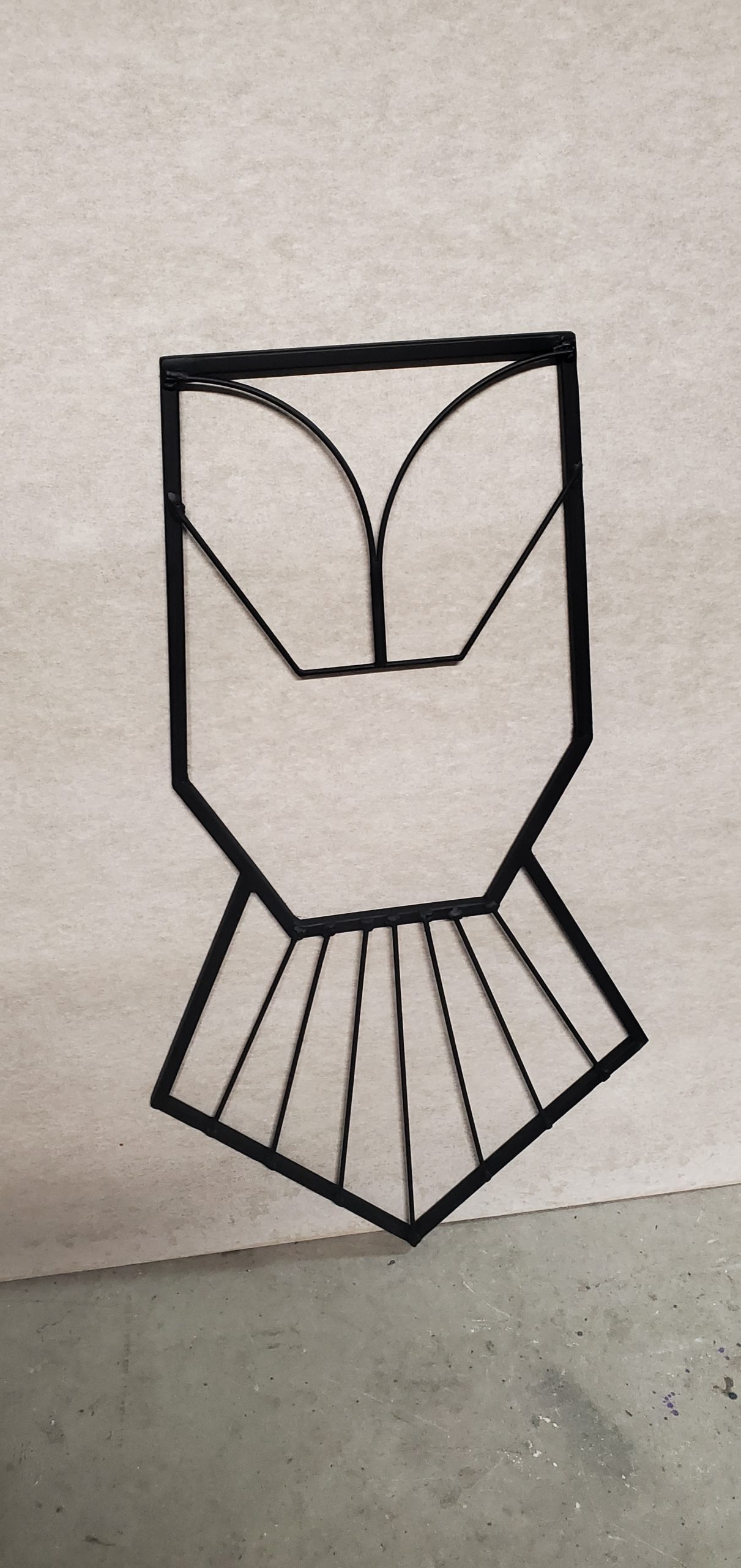
The panel frames are made of 1/2 inch square steel tubing. 3/16ths inch steel rods are used as the line details. These are MIG welded together. The steel is painted with primer, a base of black, a couple of coats of color-shifting paint, and a clear coat to protect it as much as possible. I start by creating a cardboard template.
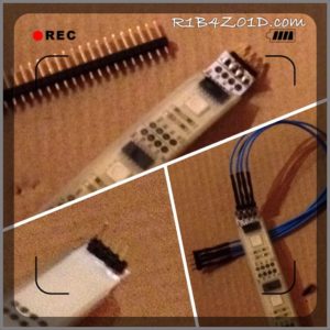
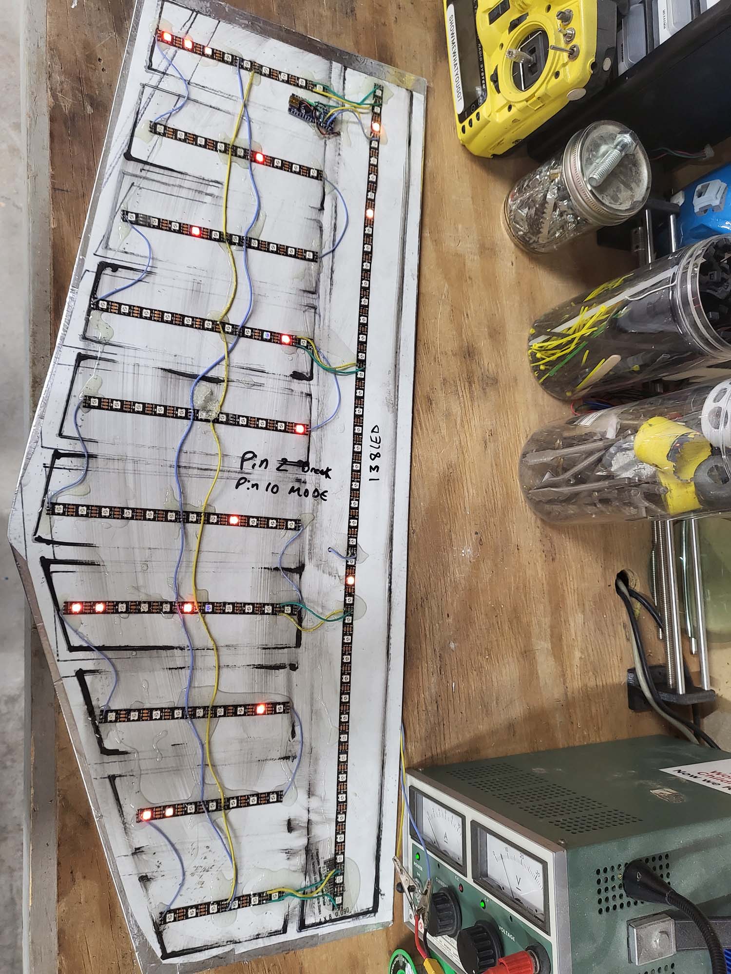
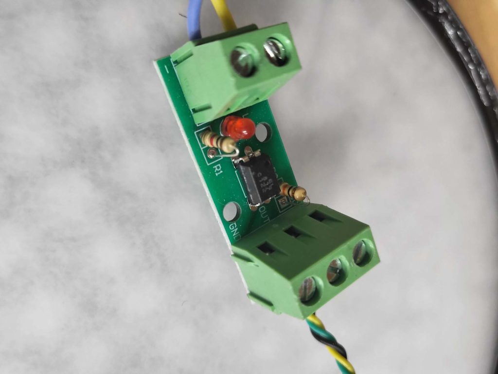
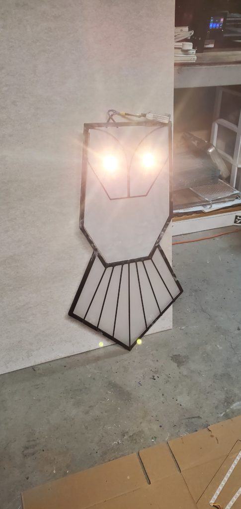
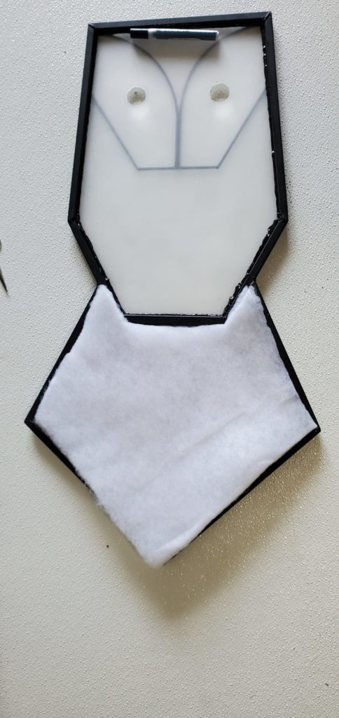
The individually addressable LED strips are mounted on fiber-reinforced plastic sheets. I used 60 WS2812B LEDs per meter strips for all panels. The strips are self-adhesive, but I added a fair amount of epoxy to hold everything together and on all the solder points for good measure. Each panel has its own microcontroller and DC-DC inverter for powering the LEDs. I did this for redundancy and if I have an issue with one panel, the remaining ones still work. The microcontrollers are simple Arduino Nanos and the inverters are XP-PoIr DTJ2024S05. I use these XP inverters at my job, and they are rock-solid, plus they are mostly sealed. I utilized M3 rivet nuts and bolts for affixing the FRP LED panels to the frames.
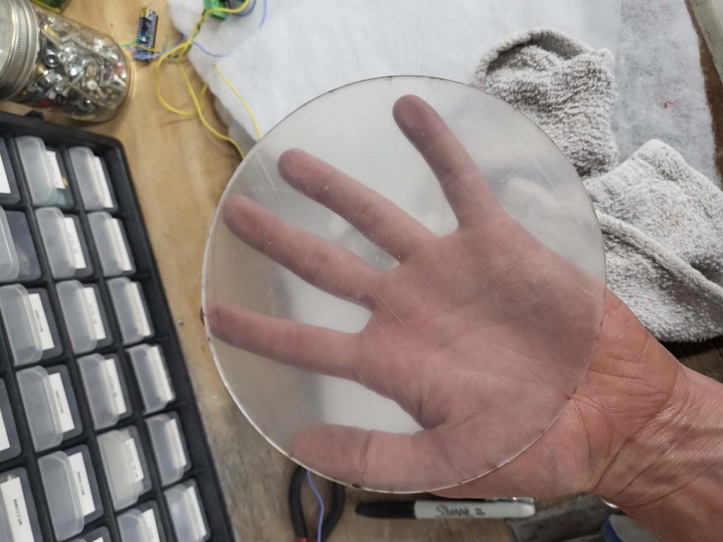
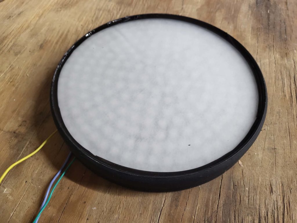
For in front of the LEDs, I cut acrylic sheets to fit inside the frame and rest on the steel rods. These are sanded on both sides to defuse the LEDs. The acrylic was secured to the frame with black silicone around the edges. The LED strips were still visible, so I had the idea to sandwich poly-fil sheets between the LED panels and the acrylic. I really loved how this look came out. It looks finished whether the LEDs are on or off, and when the LEDs are on, the polyfil does a great job at diffusing them while still allowing each LED to be visible.
Cyclcing through the modes
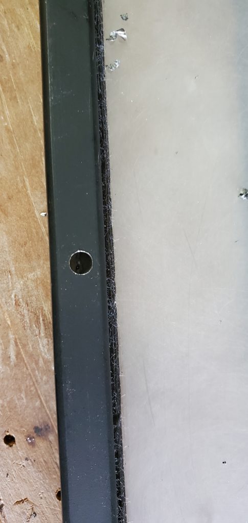
The panels are mounted to the scooter frame using the same ½ inch steel square tube. One side was flattened with a hydraulic press and a hole drilled into it for an M5 screw. The panels have M5 rivet nuts on the sides that the screws bolt to. The other side is welded to the scooter’s frame.
Squooshie SquooshRounding out the edges
After a trip to the playa in 2021 and discussing the vehicle with a couple of DMV volunteers, I knew I wanted to make some upgrades.
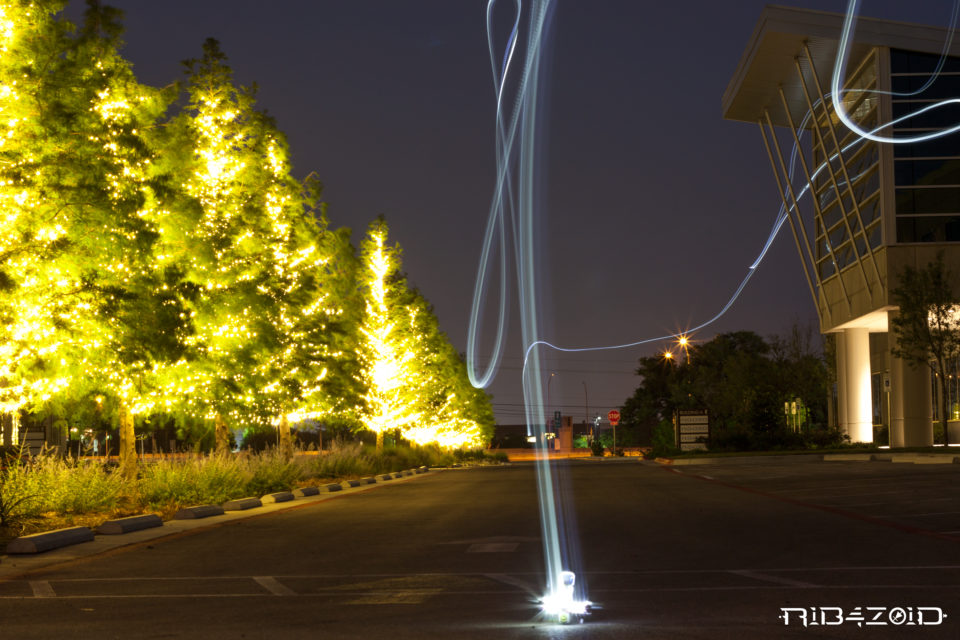
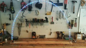
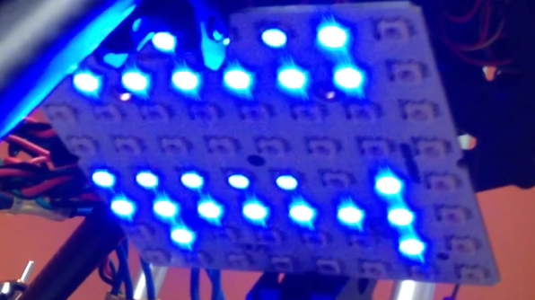
I helped fund a kickstarter project a few months back and I just received my 8×8 RGB123 LED Matrix reward for my pledge:It is a 64 (8X8) RGB123 Led matrix based on the latest WS2812B LEDs with two XT60 high current M/F connectors, two 3 pin headers, and a servo wire. For a $30 dollar pledge I am super happy with it and the overall Kickstarter experience.
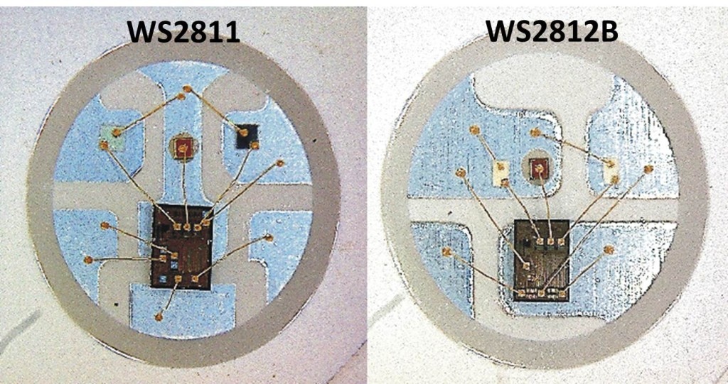
I have experience with the WS2801 chip from my IALED Pants project and it amazes me that only a few years later the led has the addressing ic embedded right in to it. The main differences for me for using the WS2812 over WS2801 is the WS2812 only needs one data line and can work at 8 or 16 megahertz. The WS2812 does not use the SPI protocol like the ws2801 therefore it does not need a clock line.
WS2812 LED modules run at 800khz, not the typical 400khz protocol available on ws2811 modules. This equates to twice the speed, allowing programs to communicate with WS2812 much faster. WS2811 and WS2812 require each color to be pre computed. The program can’t compute the 1st, color send it and then move to the next color. Instead, each color needs to be computed, buffered and send when all colors are computed. This can lead to a limitation depending on the controller being used. Depending on the library being used, each led typically takes up 4 bytes of EEPROM.
This isn’t as big of a limitation as one would think because you always have the ability to run multiple strips in parallel. The limit of strips is limited by the number of available pins. I recommend using ws2812 or ws2811 for all projects going forward unless you plan to use the SPI port. For instance if you wish to use a Raspberry Pi as a controller I recommend using WS2801 LEDs.
Over all I am very happy with the quality of the RGB123 LED Matrix and I hope to order a few more in the coming months. I really want to order on 16×16 matrix.


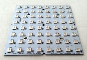 It is a 64 (8X8) RGB123 Led matrix based on the latest WS2812B LEDs with two XT60 high current M/F connectors, two 3 pin headers, and a servo wire. For a $30 dollar pledge I am super happy with it and the overall