I received my 8X8 RGB123 LED Matrix

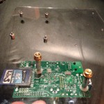
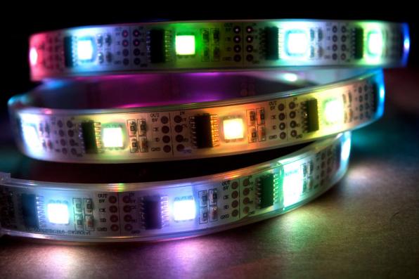
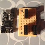
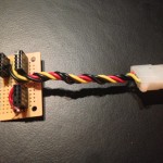
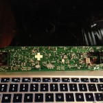
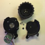
I helped fund a kickstarter project a few months back and I just received my 8×8 RGB123 LED Matrix reward for my pledge:RGB123 LED Matrix
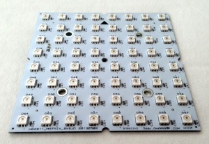
It is a 64 (8X8) RGB123 Led matrix based on the latest WS2812B LEDs with two XT60 high current M/F connectors, two 3 pin headers, and a servo wire. For a $30 dollar pledge I am super happy with it and the overall Kickstarter experience.


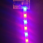
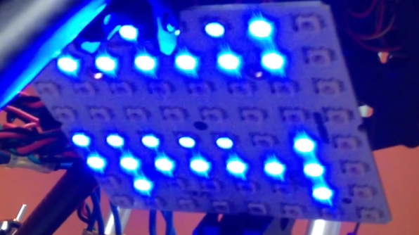
Here is a little demo of the RGB123 LED Matrix

I have experience with the WS2801 chip from my IALED Pants project and it amazes me that only a few years later the led has the addressing ic embedded right in to it. The main differences for me for using the WS2812 over WS2801 is the WS2812 only needs one data line and can work at 8 or 16 megahertz. The WS2812 does not use the SPI protocol like the ws2801 therefore it does not need a clock line.

20140106-153607.jpg

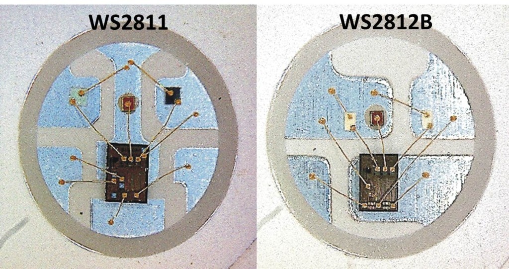
WS2812 LED modules run at 800khz, not the typical 400khz protocol available on ws2811 modules. This equates to twice the speed, allowing programs to communicate with WS2812 much faster. WS2811 and WS2812 require each color to be pre computed. The program can’t compute the 1st, color send it and then move to the next color. Instead, each color needs to be computed, buffered and send when all colors are computed. This can lead to a limitation depending on the controller being used. Depending on the library being used, each led typically takes up 4 bytes of EEPROM.


Board EEPROM Bytes Number of LEDs
Teensy 2.0 1024 256
Teensy++ 2.0 4096 1024
Teensy 3.0 2048 512
Teensy 3.1 2048 512
Digispark 512 10
DigiX 4096 1024
Teensy 2.0 1024 256
Teensy ++ 2.0 4096 1024
Teensy 3.0 2048 512
Teensy 3.1 2048 512
Uno 1024 256
Due 524 131
Leonardo 1024 256
Mega 2560 4096 1024
Mega ADK 4096 1024
Micro 1024 256
Mini 1024 256
Nano ATmega168 524 131
Nano ATmega328 1024 256
Ethernet 1024 256
Esplora 1024 256
ArduinoBT 1024 256
Fio 1024 256
Pro ATmega168 524 131
Pro ATmega328 1024 256
Pro Mini 524 131
LilyPad 524 131
LilyPad USB 1024 256

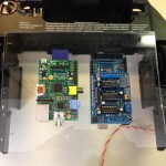
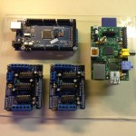
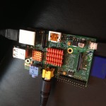
This isn’t as big of a limitation as one would think because you always have the ability to run multiple strips in parallel. The limit of strips is limited by the number of available pins. I recommend using ws2812 or ws2811 for all projects going forward unless you plan to use the SPI port. For instance if you wish to use a Raspberry Pi as a controller I recommend using WS2801 LEDs.

Over all I am very happy with the quality of the RGB123 LED Matrix and I hope to order a few more in the coming months. I really want to order on 16×16 matrix.

Raspberry Pi Robot Build 4: Suspension Upgrade & Electronics Mounting Board

In this post, you will see my progress on the physical construction of my raspberry pi robot starting from a used Roomba 435. After hours of testing, I discovered my Roomba 435‘s logic board had an old firmware and would not allow me to communicate with it via it’s serial command interface without paying to flash it with version 2.1. I figured for the price to flash the logic board (ship both ways plus the service charge) and considering I already had an Arduino Mega to use as the micro-controller, it would be cheaper not to use the OEM logic board (for right now).

I first purchased a seeed studio motor shield at Radio Shack to test out my concept. After a successful proof of concept:

POC Motor Shield

Review & POC Video: 
[youtube http://youtu.be/F4f7SolCGBg]

I ordered two motor shields to control each of the OEM DC motor units. Each shield can power 4 DC motors or 2 stepper motors (or 1 stepper motors & 2 DC motors) as well as 2 servos, so I have plenty of flexibility to expand the project. I will be using the stock DC motors, wheels and gears. I will eventually integrate the OEM wheel encoders. Utilizing the wheel encoders will allow me to accurately sense direction, distance, velocity and acceleration.

After figuring out what components I was going to use, I needed to build an electronics mounting board so that I could keep all the parts organized and safe. I wanted to mount the Raspberry Pi, two motor controllers and the Arduino Mega in the empty space where all the vacuum parts used to be. I used a spare piece of plexiglass as the mounting platform. I placed the components in the best configuration possible and marked all the mounting holes with a marker. I drilled out each hole to mount different size standoffs for the component to mount to.

Once I had all the components securely mounted on the plexiglass, I had to secure the plexiglass to the Roomba’s frame. I used a couple of screws to hold it initially, but then remembered I had some polymorph left over from another project. The  polymorph is what is really holding the two pieces together. If you have never used it before, I would recommend grabbing some and start playing around.

The OEM springs that came in the Roomba 435 were too weak and needed to be much more rigged to hold the weight of the new electronics plus future add-ons. First, I removed the front spring completely and secured it by jamming polymorph into the mounting hole. The wheel still pivots, but no longer moves up and down. After fixing the front wheel, I replaced both rear springs with much larger ones. The rear suspension is still flexible, but it is much more rigid and sturdy now.

PiRobot Build 2: Adding Heat Sink & Temp Tests Raspberry Pi

I wanted to add heat sinks to keep the core Raspberry Pi temperature down while running cpu intensive processes. I have made some huge strides on the PiRobot project, I just need get may act together and make all the posts. Here is one of the last things I have done but it is going to be an easy blog post so I decided to publish this 1st.

I checked the Raspberry Pi core and external temperatures during 3 stages for both OEM and after the heat sinks were installed. As a control the device had an external temperature reading of 24.7°c off and unplugged. While Idling the OEM average core temperature was 43.29°c with a max of 44.4°c and a min of 42.2°c. The external temperature was just about 40°c.

The 1st load test I did was using Python finding prime numbers. It found 78497 primes in 5:42.61 but the CPU usage never went above 25% so I needed to find another test. After reading how I can use the basic calculator as the CPU benchmark I modified the original equation so that the CPU would be maxed out for at least 20 minutes:

 $time echo "scale=10000; a(3)*8" | bc -l

You may need to install the bc package:

 $sudo apt-get install bc

After 20 minuets of 100% CPU usage the average core temperature was 45.38°c on the OEM Raspberry Pi, it maxed out at 47.1°c.

After installing the heat sinks on the Raspberry Pi the core and external temperatures definitely dropped. After idling for 24 hours the external temperature was 38.5°c and the  core temperature was 39.5°c. After ruining the same bc equation for over 20 minutes (100% CPU usage) the average core temperature was 42.67°c with a miximum temerature of 44.4°c. For more details of temperatures download this: HeatSinkTests.xls.

Raspberry Pi Heat Sink:

raspberry pi

Raspberry Pi Robot Part 1: Roomba Teardown

Updated: More Photos

In anticipation of receiving my Raspberry Pi

Raspberry Pi

The Raspberry Pi is a credit-card-sized single-board computer developed in the UK by the Raspberry Pi Foundation with the intention of raspberry pi

this week I wanted to get a head start one of my next projects, PiRobot. PiRobot is going to be a web site controlled robot powered by a Raspberry Pi. The website will utilize webiopi to control the Raspberry Pi’s general purpose in/output ins (GPIO). For network connectivity I will be using a high gain USB WIFI network card. I will add a location to place and iPhone with tethering If I need to control the PiRobot outside of a local WIFI.

I am going to recycle an old iRobot Roomba to uses as the main driving unit. This post shows my teardown of the iRobot Roomba in preparation for this project. To save on weight I wanted to remove all the components that I would not be utilizing. To start I only need the frame, wheels, motor, suspension and the logic board.

I will be interfacing the Raspberry Pi with the iRobot Roombi’s built in logic board via serial using pyrobot. This will allow me control each driving motor as well as interface with all built in sensors and the other motors (that I just removed). If I can’t get the serial connection to work I will take some tips from Ben J. I will more then likely be using the Raspberry Pi’s GPIO but I can also utilize the additional ports on the Roomba’s logic board to control the accessories I plan to add once I get the PiRobot up and moving.

I first want add a tilt and pan high definition webcam to have the ability to drive it with out seeing the unit. The next accessory will be a powered speaker and use the webcam’s microphone for two way audio communication. Then I will be adding an ultrasonic proximity sensors on each side of the robot to detect obstacles while controlling the unit remotely. These sensors have a sensing range from about 5 inches to about 15 feet with a resolution of about .1 of an inch.

The website will stream the video from the webcam as well as have controls to operate the PiRobot. It will display two virtual joystick, one to move the PiRobot and one to control the tilting and panning of the webcam. I will also be including the ability to use the keyboards standard ←↕→ keys and a mouse or possibly even a joystick. I am thinking of having the site display a 3d top view of the Raspberry Pi Robot with graphical feedback from all the sensors and to display the position of the webcam’s tilt and pan. Once all that is done I will be adding an arm and hand to it extend the functionality.


IALEDPants v0.2b WS2801 Speed Test

Here is the 2nd demo of my new WS2801 individually addressable RGB LED pants. The pants are lined with WS2801 RGB LED strips. The strips are controlled by an Arduino nano and powered by 4 AA batteries. I wanted to create this video quick before I add some additional features. I plan to add a microphone to code them to be noise active as well as add a pot to control the intensity of the LEDs.

WS2801

ws2801

IALEDPants v0.1b ws2801 Color Test

Here is the color demo of my new ws2801 individually addressable RGB LED pants. The pants are lined with WS2801 RGB LED strips. The strips are controlled by an Arduino and powered by 4 AA batteries. I wanted to create this video quick before I add some additional features. I plan to add a microphone to code them to be noise active as well as add a pot to control the intensity of the LEDs. Check out the website http://R1B4Z01D.com and subscribe to check out my other projects and any update to this.

My Arduino Code:

https://gist.github.com/r1b4z01d/4757278

WS2801 LED Strips:

ws2801

IALEDPants v0.1b: WS2801 + Arduino

Here is the demo of my new WS2801 individually addressable RGB LED pants. The pants are lined with WS2801 RGB LED strips. The strips are controlled by an Arduino and powered by 4 AA batteries. I wanted to create this video quick before I add some additional features. I plan to add a microphone to code them to be noise active as well as add a pot to control the intensity of the LEDs.

WS2801

ws2801