
3D Printing Test – Calibration & Gifts
I have been 3D printing test objects for the past few weeks and my progress is getting better after each object I print. The main variable in successfully printing a quality object is making sure the heated bed is level to the print head. The first object I tried printing was the 5mm Calibration Cube Steps:
These were the 1st, 2nd & 3rd Print: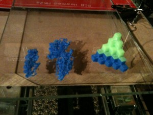
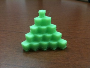
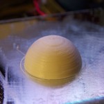
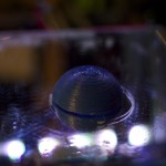
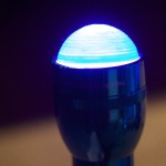
The qbert design is one of the first 3d printing test objects most people print because it is extremely helpful in calibrating each axis. Each cube in the design should be 5MM3. Once the object is printed, I used a digital caliper to validate that each axis is moving (printing) the correct distances. After I correctly calibrated the axes; I printed my second calibration object: the dome.
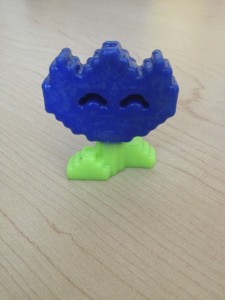
After calibrating using the 3D printing test objects, I started printing and designing more practical objects. The 1st was a gift to my wife, Knap’s Mario Flower:
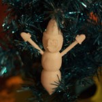
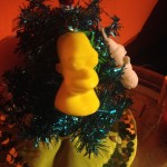
 Thingiverse had an ornament contest and I wanted to get involved, so I designed a 3D model of MR.Hanky the Christmas Poo. This was my first design that I printed and I tell you, it is a weird feeling designing something in software then printing it off a few hours later. We are absolutely living in the future. I uploaded the model to my Thingiverse profile so you can download and print it yourself.
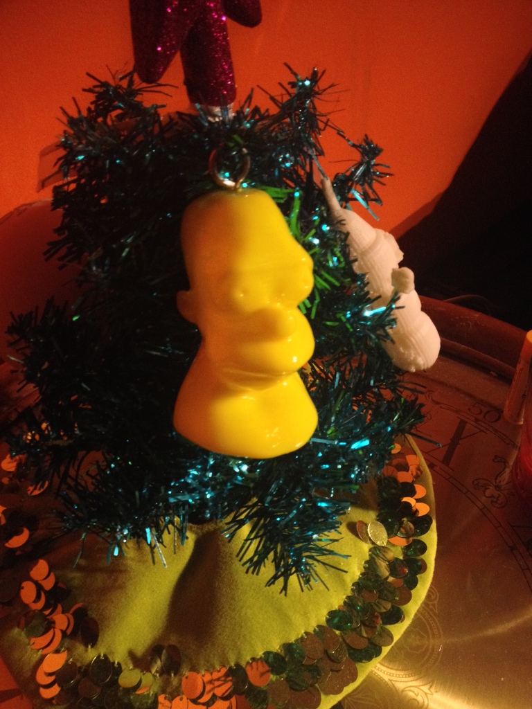
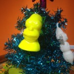
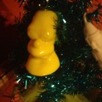
For Christmas, I printed off a Homer bust for my bother:
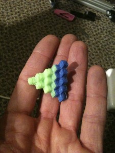
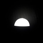
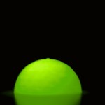
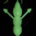
Then I printed off a snowflake ordainment for a close friend.
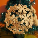
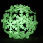

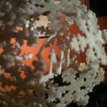

My first attempt was with yellow, but I quickly thought, “It’s not a good idea to make yellow snow.”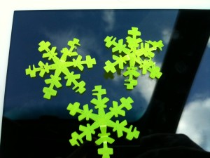
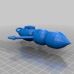
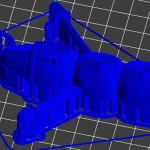
I also printed a gift for my wife’s Reddit Secret Santa:
I hope you enjoyed viewing all my 3D Printing test objects. My next post should be primarily about my printer design.
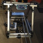
My 3D Printer Design (Prototype)
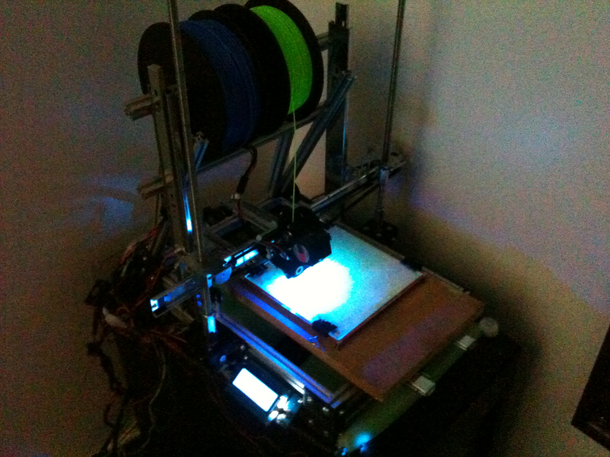
After pricing out the parts needed to finish the MindelMax 1.5 3D printer design and realizing I want to use rail slides instead of linear bearings and rods, I decided to develop a custom design. This post includes photos and descriptions from the alpha stage of the design. I am finalizing the bata design right now and a lot of what you see in this post has been changed. After a few more tests I will be releasing the design with an open source.
All designs are shared under the CC BY-NC-ND 4.0 licensing.

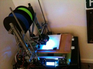
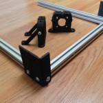
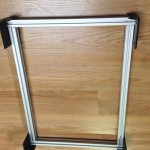
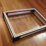
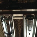
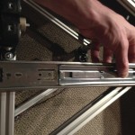
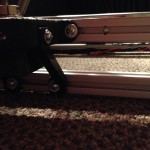
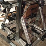
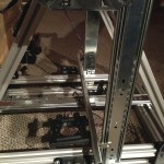
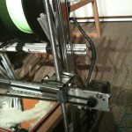
I constructed the frame of the MindelMax 1.5 3D printer design:
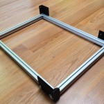
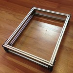
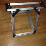
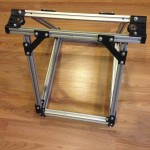
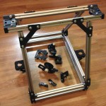
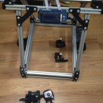
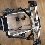
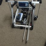
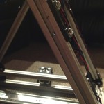
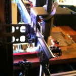
Y & Z Axes:
The current 3D printer design is limited to the 200mm by 200mm hotbed, but in the final design the x-axis has 300mm of printing range. The y-axis will be much larger; I am aiming for 600 to 800mm, but the design could theoretically support double or triple that. After deciding on the rails, I started measuring and drilling holes to accommodate them. I started with the y-axis; the y-axis holds the hot bed and the entire bed moves on two rails. I then moved to the z-axis, with a rail on each side (this might change). I used a M10 coupler bolt as a coupler for the threaded rods and stepper motor.
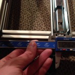
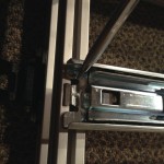
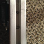
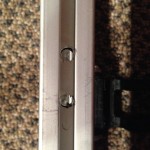
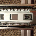
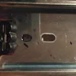
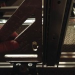
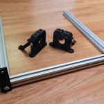
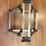
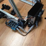
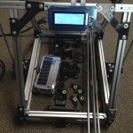
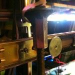
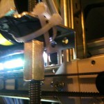
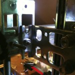
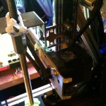
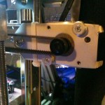
X-Axis:
Each bracket has to mount a z-axis coupler bolt, a mount for one side of the x-axis rail, a mount for a z-axis rail, a hole for a bearing on the left bracket and a stepper motor mount on the right. Before I could print the new 3d printer design parts, I had to mock them up with random metal parts I had. I used my drill press to drill out the hole for the threaded rods and holes to mount the separate pieces together. I used SteelStik Epoxy Putty to hold a M10 coupler bolt to the bracket. These pictures were taken right before finalizing the beta version of the brackets. This was a good thing because the brackets were falling apart, hence the zip ties.
My next post will be the test prints.
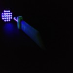
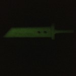
Playing Around With Modul8
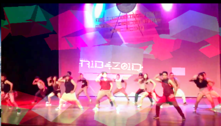
The idea behind this is to use non-traditional shapes as a screen for a unique visual performance. Using Modul8 I was able to map out each side of the cube and the long rectangle as it’s own screen.
Modul8
has been very easy to learn and there are plenty of tutorials all over YouTube and the internet in general. I plan to eventually synch Ableton and Modul8 together to allow me to trigger audio clips and have specific visuals designed for the specific clip play as well.
