Project No Excuses : Week 1
Get Ready For Fall

September-OSP-Race
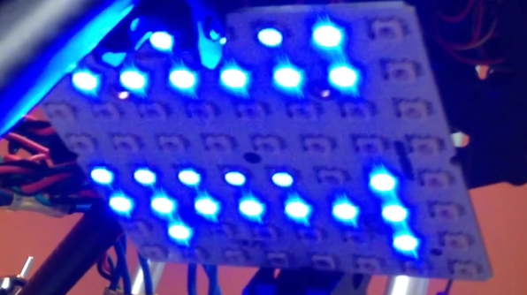
I received my 8X8 RGB123 LED Matrix
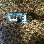
I helped fund a kickstarter project a few months back and I just received my 8×8 RGB123 LED Matrix reward for my pledge: It is a 64 (8X8) RGB123 Led matrix based on the latest WS2812B LEDs with two XT60 high current M/F connectors, two 3 pin headers, and a servo wire. For a $30 dollar pledge I am super happy with it and the overall Kickstarter experience.
Here is a little demo of the RGB123 LED Matrix
I have experience with the WS2801 chip from my IALED Pants project and it amazes me that only a few years later the led has the addressing ic embedded right in to it. The main differences for me for using the WS2812 over WS2801 is the WS2812 only needs one data line and can work at 8 or 16 megahertz. The WS2812 does not use the SPI protocol like the ws2801 therefore it does not need a clock line.
WS2812 LED modules run at 800khz, not the typical 400khz protocol available on ws2811 modules. This equates to twice the speed, allowing programs to communicate with WS2812 much faster. WS2811 and WS2812 require each color to be pre computed. The program can’t compute the 1st, color send it and then move to the next color. Instead, each color needs to be computed, buffered and send when all colors are computed. This can lead to a limitation depending on the controller being used. Depending on the library being used, each led typically takes up 4 bytes of EEPROM.
| Board | EEPROM Bytes | Number of LEDs |
| Teensy 2.0 | 1024 | 256 |
| Teensy++ 2.0 | 4096 | 1024 |
| Teensy 3.0 | 2048 | 512 |
| Teensy 3.1 | 2048 | 512 |
| Digispark | 512 | 10 |
| DigiX | 4096 | 1024 |
| Teensy 2.0 | 1024 | 256 |
| Teensy ++ 2.0 | 4096 | 1024 |
| Teensy 3.0 | 2048 | 512 |
| Teensy 3.1 | 2048 | 512 |
| Uno | 1024 | 256 |
| Due | 524 | 131 |
| Leonardo | 1024 | 256 |
| Mega 2560 | 4096 | 1024 |
| Mega ADK | 4096 | 1024 |
| Micro | 1024 | 256 |
| Mini | 1024 | 256 |
| Nano ATmega168 | 524 | 131 |
| Nano ATmega328 | 1024 | 256 |
| Ethernet | 1024 | 256 |
| Esplora | 1024 | 256 |
| ArduinoBT | 1024 | 256 |
| Fio | 1024 | 256 |
| Pro ATmega168 | 524 | 131 |
| Pro ATmega328 | 1024 | 256 |
| Pro Mini | 524 | 131 |
| LilyPad | 524 | 131 |
| LilyPad USB | 1024 | 256 |
This isn’t as big of a limitation as one would think because you always have the ability to run multiple strips in parallel. The limit of strips is limited by the number of available pins. I recommend using ws2812 or ws2811 for all projects going forward unless you plan to use the SPI port. For instance if you wish to use a Raspberry Pi as a controller I recommend using WS2801 LEDs.
Over all I am very happy with the quality of the RGB123 LED Matrix and I hope to order a few more in the coming months. I really want to order on 16×16 matrix.
I built a podium for my wife’s classroom.

3D Printing Test – Calibration & Gifts
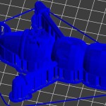
I have been 3D printing test objects for the past few weeks and my progress is getting better after each object I print. The main variable in successfully printing a quality object is making sure the heated bed is level to the print head. The first object I tried printing was the 5mm Calibration Cube Steps:
These were the 1st, 2nd & 3rd Print:


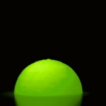
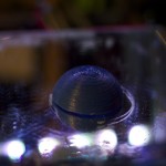
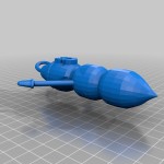
The qbert design is one of the first 3d printing test objects most people print because it is extremely helpful in calibrating each axis. Each cube in the design should be 5MM3. Once the object is printed, I used a digital caliper to validate that each axis is moving (printing) the correct distances. After I correctly calibrated the axes; I printed my second calibration object: the dome.
After calibrating using the 3D printing test objects, I started printing and designing more practical objects. The 1st was a gift to my wife, Knap’s Mario Flower:
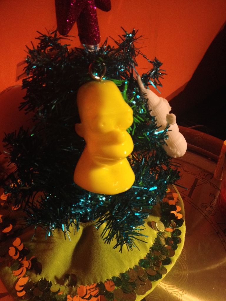
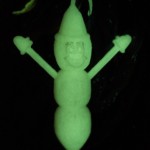
 Thingiverse had an ornament contest and I wanted to get involved, so I designed a 3D model of MR.Hanky the Christmas Poo. This was my first design that I printed and I tell you, it is a weird feeling designing something in software then printing it off a few hours later. We are absolutely living in the future. I uploaded the model to my Thingiverse profile so you can download and print it yourself.
For Christmas, I printed off a Homer bust for my bother:
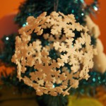
Then I printed off a snowflake ordainment for a close friend.
My first attempt was with yellow, but I quickly thought, “It’s not a good idea to make yellow snow.”
I also printed a gift for my wife’s Reddit Secret Santa:
I hope you enjoyed viewing all my 3D Printing test objects. My next post should be primarily about my printer design.
My 3D Printer Design (Prototype)
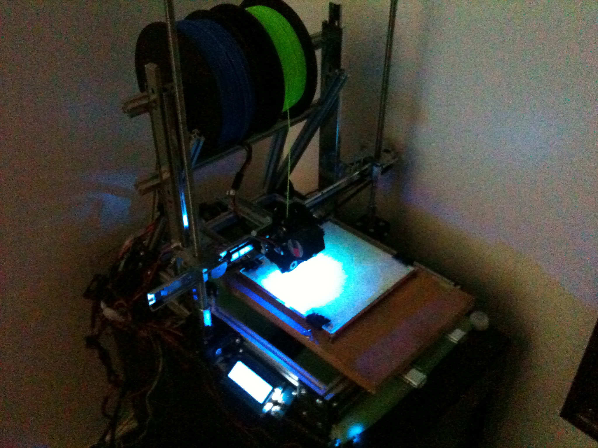
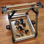
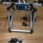
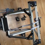
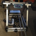
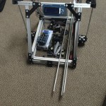
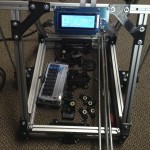
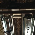
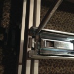
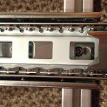
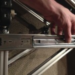
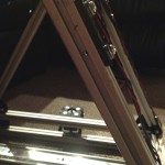
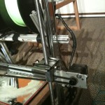
After pricing out the parts needed to finish the MindelMax 1.5 3D printer design and realizing I want to use rail slides instead of linear bearings and rods, I decided to develop a custom design. This post includes photos and descriptions from the alpha stage of the design. I am finalizing the bata design right now and a lot of what you see in this post has been changed. After a few more tests I will be releasing the design with an open source.
All designs are shared under the CC BY-NC-ND 4.0 licensing.

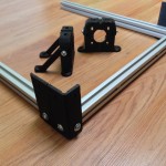
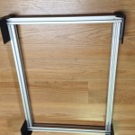
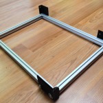
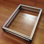
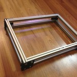
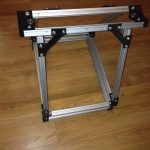
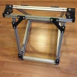
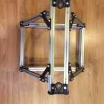
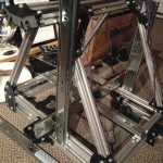
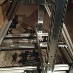
I constructed the frame of the MindelMax 1.5 3D printer design:
Y & Z Axes:
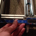
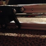
The current 3D printer design is limited to the 200mm by 200mm hotbed, but in the final design the x-axis has 300mm of printing range. The y-axis will be much larger; I am aiming for 600 to 800mm, but the design could theoretically support double or triple that. After deciding on the rails, I started measuring and drilling holes to accommodate them. I started with the y-axis; the y-axis holds the hot bed and the entire bed moves on two rails. I then moved to the z-axis, with a rail on each side (this might change). I used a M10 coupler bolt as a coupler for the threaded rods and stepper motor.
X-Axis:
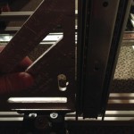
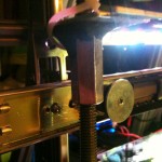
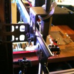
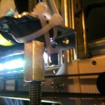
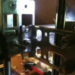
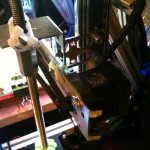
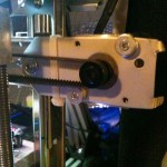
Each bracket has to mount a z-axis coupler bolt, a mount for one side of the x-axis rail, a mount for a z-axis rail, a hole for a bearing on the left bracket and a stepper motor mount on the right. Before I could print the new 3d printer design parts, I had to mock them up with random metal parts I had. I used my drill press to drill out the hole for the threaded rods and holes to mount the separate pieces together. I used SteelStik Epoxy Putty to hold a M10 coupler bolt to the bracket. These pictures were taken right before finalizing the beta version of the brackets. This was a good thing because the brackets were falling apart, hence the zip ties.
My next post will be the test prints.
New Category: 3D Printing – Electronics
I am happy to announce I am adding a new category to the blog: 3D printing. For years I have wanted a 3D printer but I never found exactly what I wanted. I came across a cragslist post for a lot of 3D printer parts for a great price and I had to take the plunge. The seller was trying to build a MindelMax 1.5. He acquired about 90% of the parts but never started the build.

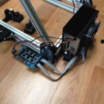
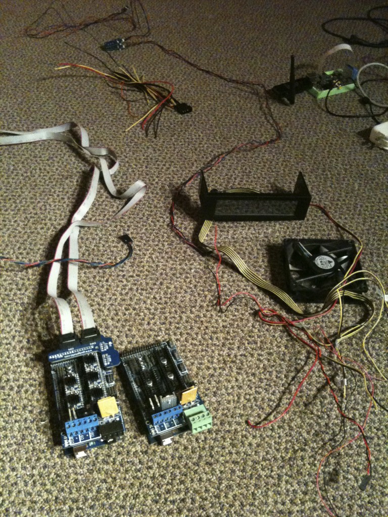
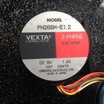
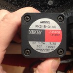
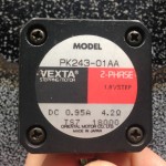
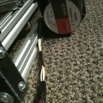
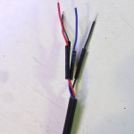
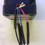
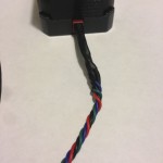
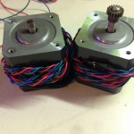
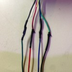
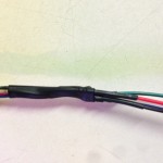
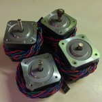
The lot of parts excluded all the Aluminum extrusions bars, all the plastic parts, RepRap Arduino Mega Pololu Shield (RAMPS 1.4), an Arduino Mega 2560, 5 GADGETS3D A4988 G3D Drivers, an LCD and SHIELD v1.0, 214mmx214mm MK2a PCB Heated Bed and a few other parts. He also through in 4 Vexta high torque stepper motors (PDF)! They are 2-phase with 1.8° step angle. They were wired in a Unipolar configuration so I had to had to rewire them to be bipolar to work with the G3D A4988 Pololu Drivers. I used this diagram.
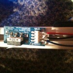
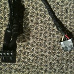
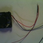
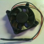
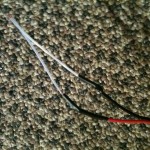
After the motors were ready I soldered leads to the mechanical endstops, a thermisitor, fan and cleaned up an old power supply to power the printer.
VDMX and Ableton Live Visuals Demo
I wanted to give you guys a little demo of what I am working on for my live performances using VDMX and Ableton live. In the 1st part of this video I show a few examples of presets I configured in VDMX. Later on I explain a little more in depth. If there is an interest I can make a step by step tutorial. Subscribe, share, Like and/or post a comment if you like what you see.
Examples of What I Produce with VDMX and Ableton:


