Updated: More Photos
In anticipation of receiving my Raspberry Pi
Raspberry Pi

this week I wanted to get a head start one of my next projects, PiRobot. PiRobot is going to be a web site controlled robot powered by a Raspberry Pi. The website will utilize webiopi to control the Raspberry Pi’s general purpose in/output ins (GPIO). For network connectivity I will be using a high gain USB WIFI network card. I will add a location to place and iPhone with tethering If I need to control the PiRobot outside of a local WIFI.
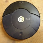
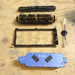
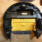
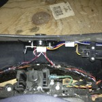
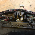
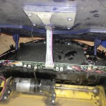
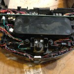
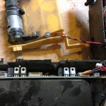
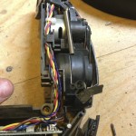
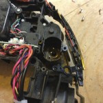
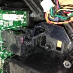
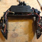
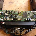
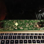
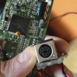
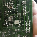
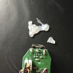
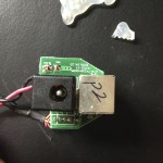
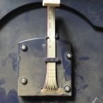
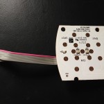
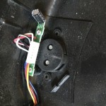
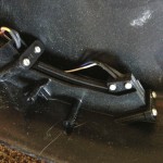
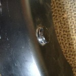
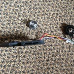
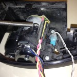
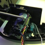
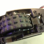
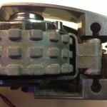
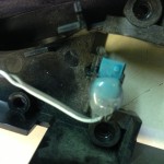
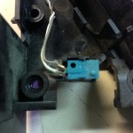
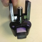
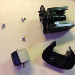
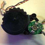
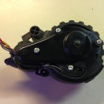
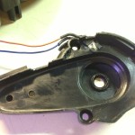
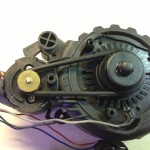
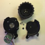
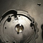
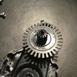
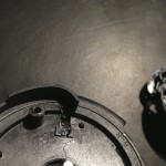
I am going to recycle an old iRobot Roomba to uses as the main driving unit. This post shows my teardown of the iRobot Roomba in preparation for this project. To save on weight I wanted to remove all the components that I would not be utilizing. To start I only need the frame, wheels, motor, suspension and the logic board.
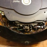
I will be interfacing the Raspberry Pi with the iRobot Roombi’s built in logic board via serial using pyrobot. This will allow me control each driving motor as well as interface with all built in sensors and the other motors (that I just removed). If I can’t get the serial connection to work I will take some tips from Ben J. I will more then likely be using the Raspberry Pi’s GPIO but I can also utilize the additional ports on the Roomba’s logic board to control the accessories I plan to add once I get the PiRobot up and moving.
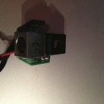
I first want add a tilt and pan high definition webcam to have the ability to drive it with out seeing the unit. The next accessory will be a powered speaker and use the webcam’s microphone for two way audio communication. Then I will be adding an ultrasonic proximity sensors on each side of the robot to detect obstacles while controlling the unit remotely. These sensors have a sensing range from about 5 inches to about 15 feet with a resolution of about .1 of an inch.
The website will stream the video from the webcam as well as have controls to operate the PiRobot. It will display two virtual joystick, one to move the PiRobot and one to control the tilting and panning of the webcam. I will also be including the ability to use the keyboards standard ←↕→ keys and a mouse or possibly even a joystick. I am thinking of having the site display a 3d top view of the Raspberry Pi Robot with graphical feedback from all the sensors and to display the position of the webcam’s tilt and pan. Once all that is done I will be adding an arm and hand to it extend the functionality.