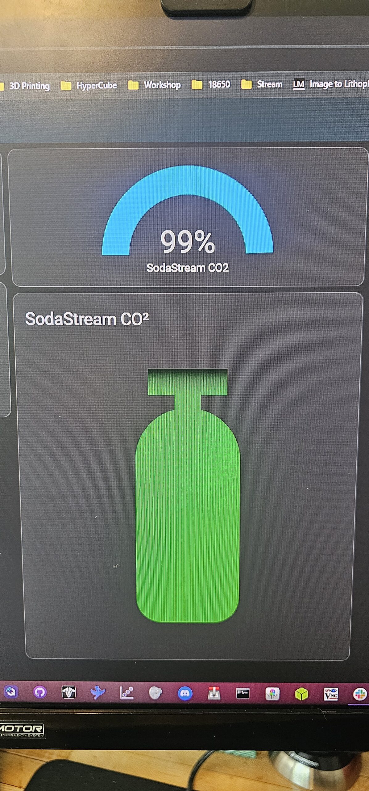
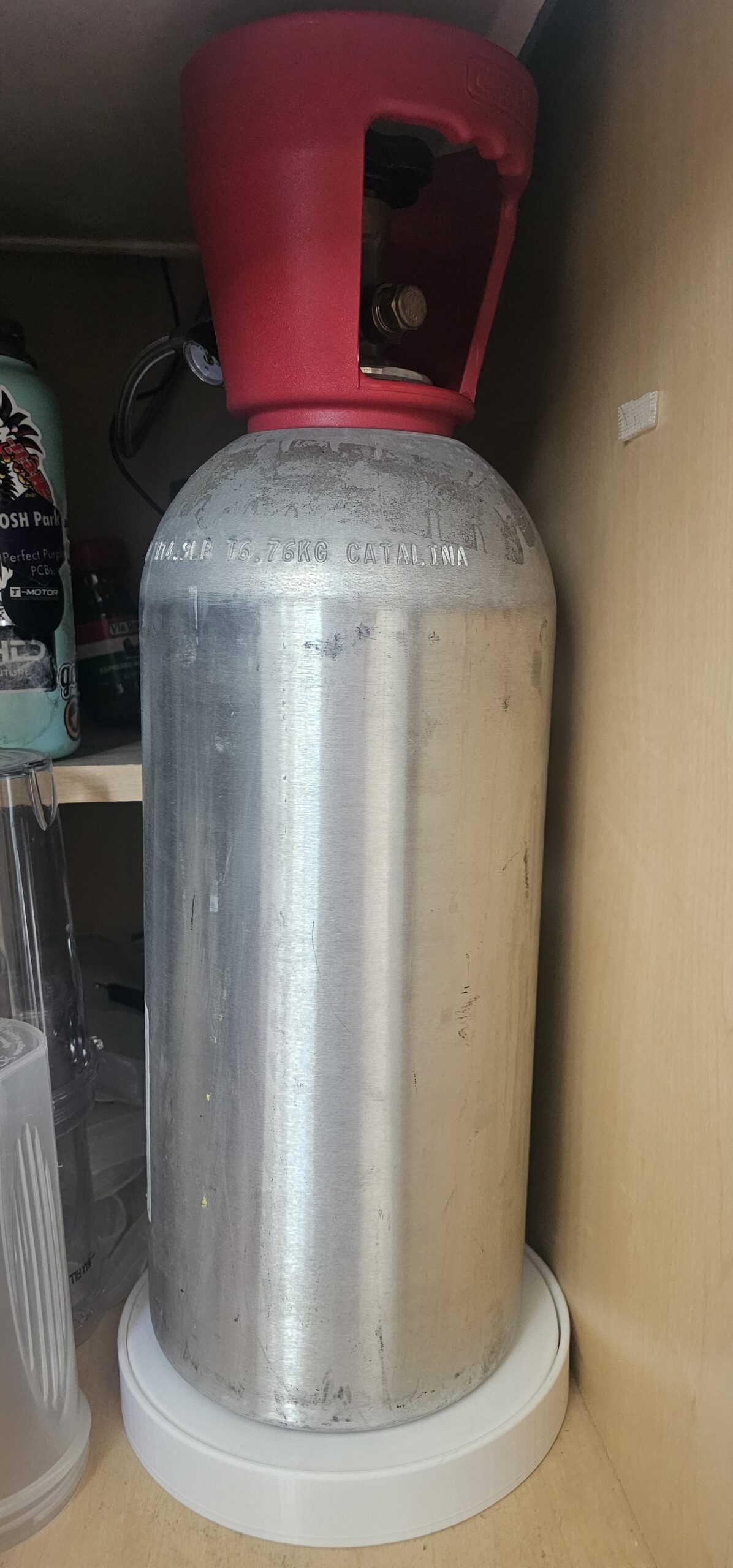
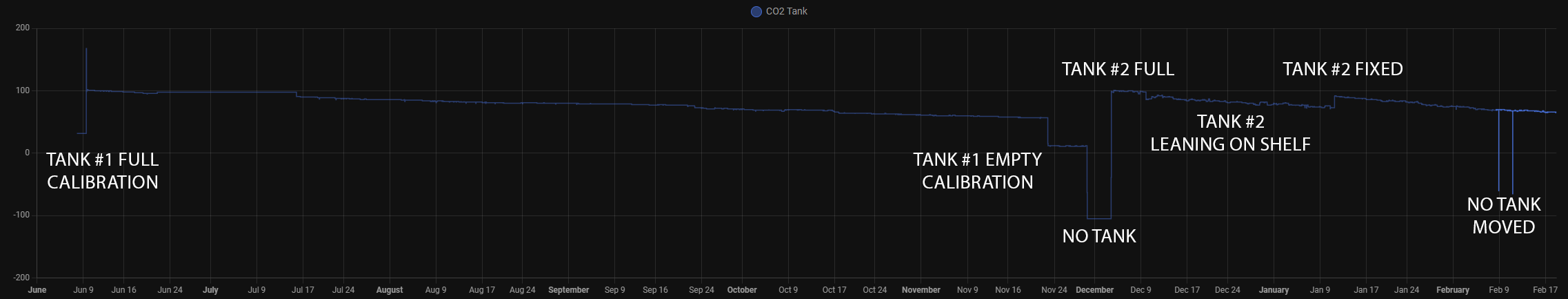
I wanted to better estimate when the CO2 tank was running out, so I designed a simple IOT device. It utilizes an EPP32, load cell and the ESPHome firmware. Home Assistant integration couldn’t have been any easier.
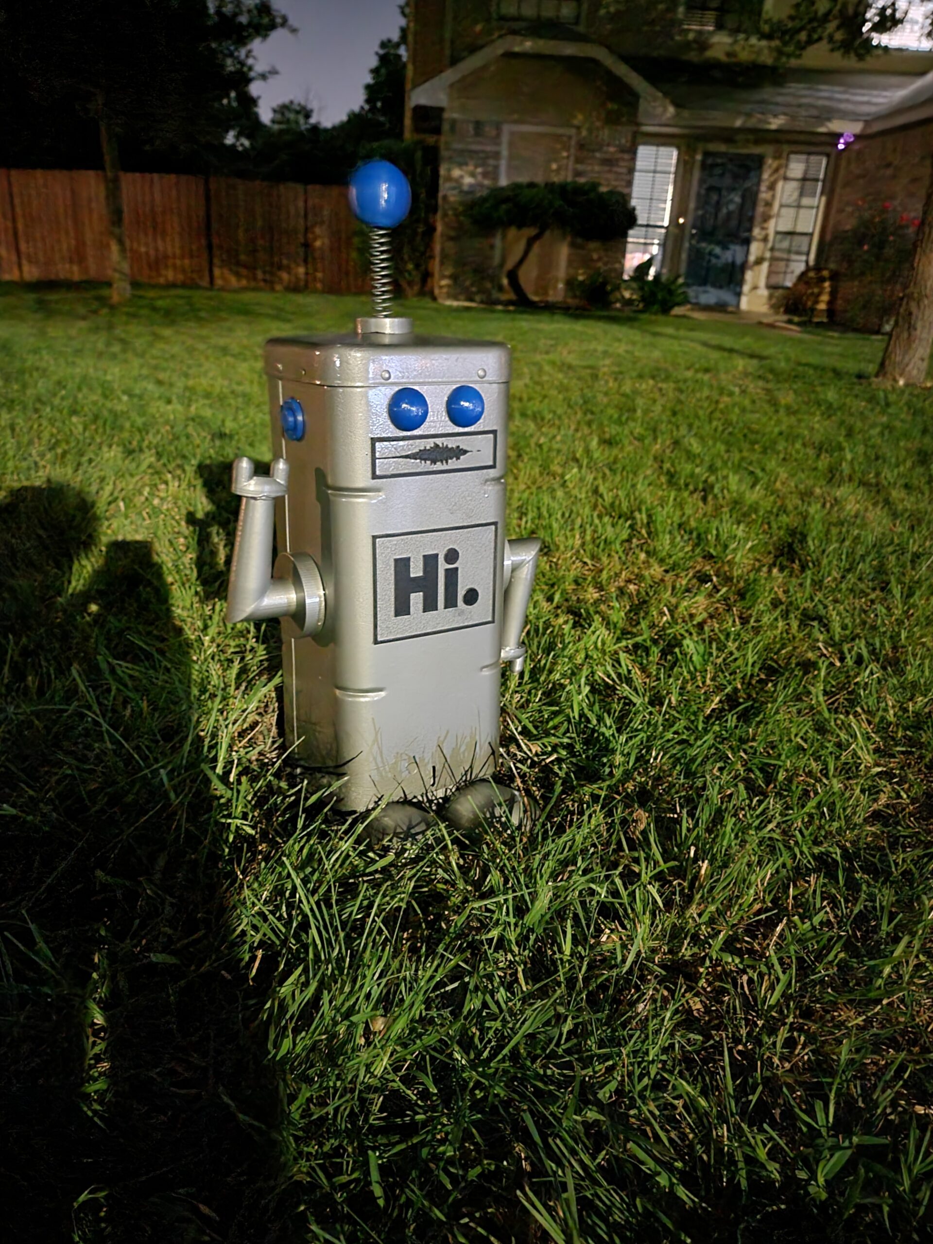
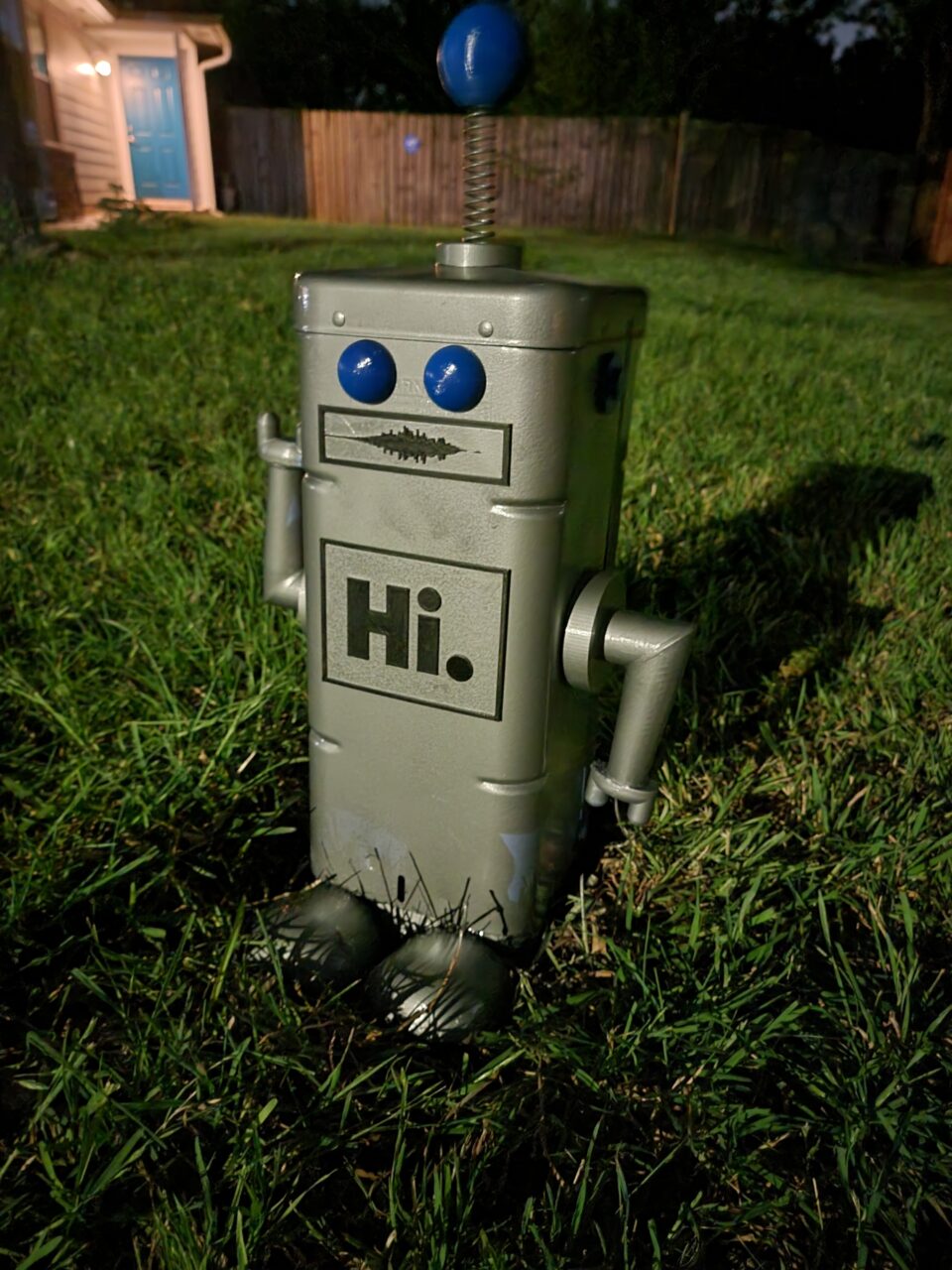
So….. we have this cable box on the property line between our house and the neighbors. I have always wanted to beautify it, so one night I did. Really it was about a week from the idea to design, 3D print, paint, and installation.
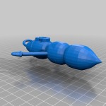
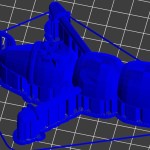
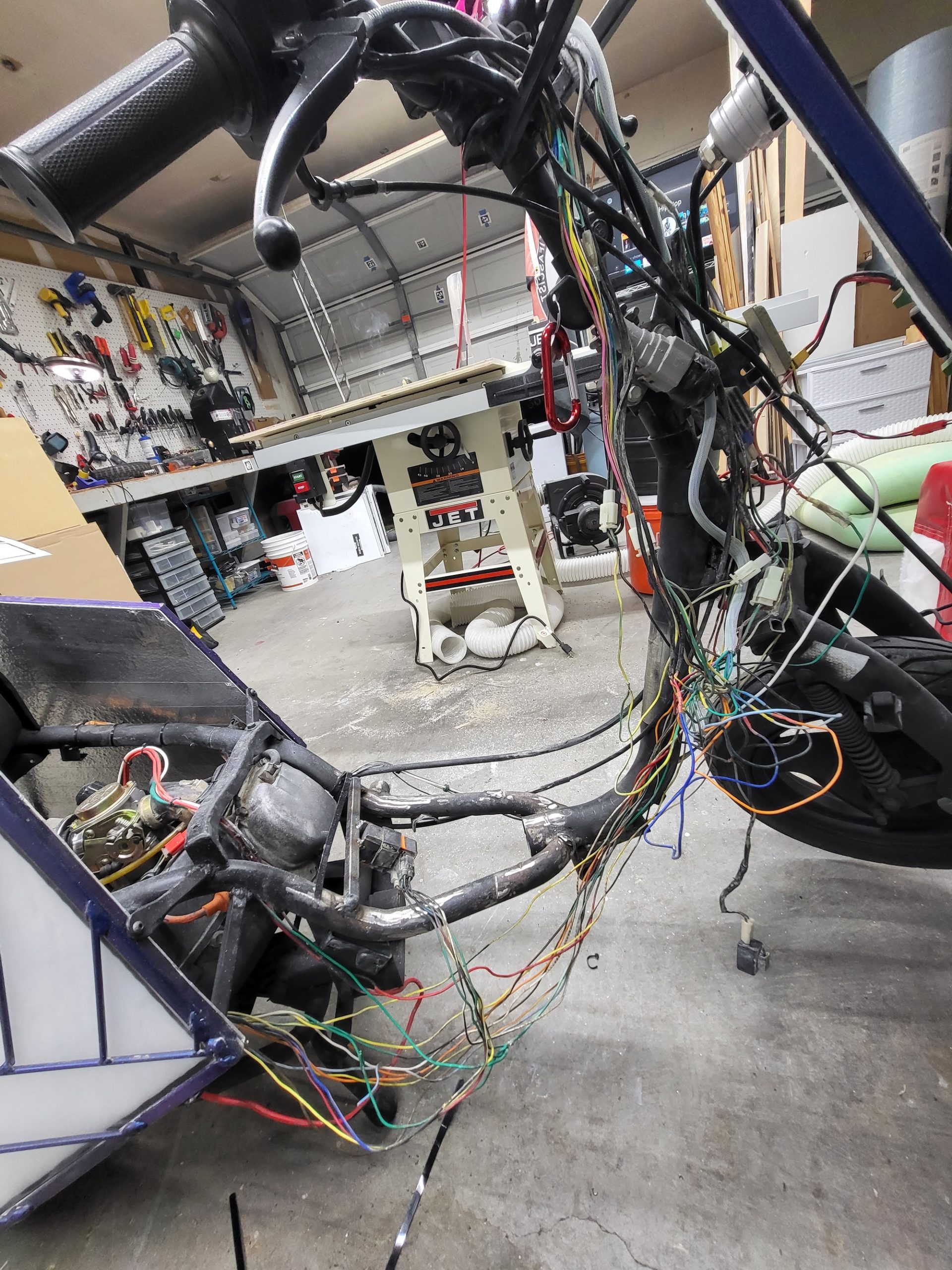
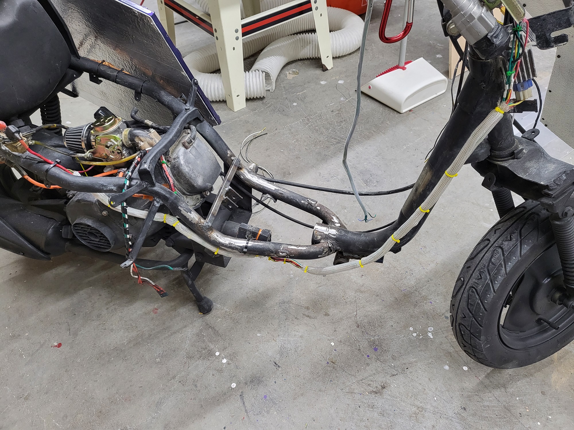
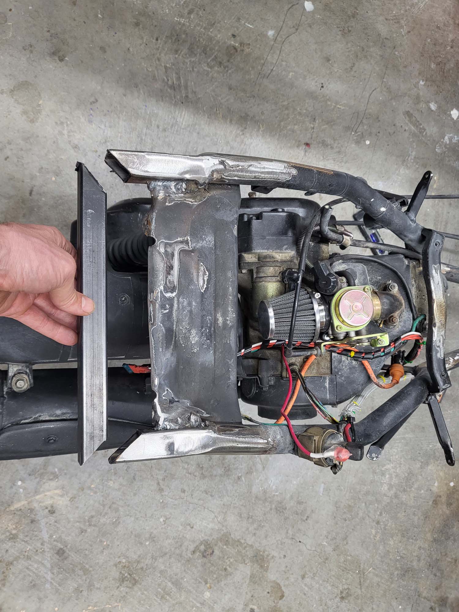
After a trip to the Playa in 2021 for Renegade Burn and discussing the vehicle with a couple of DMV volunteers, I knew I wanted to make some upgrades. Before that could start, I needed to give it a good cleaning and look for any issues.
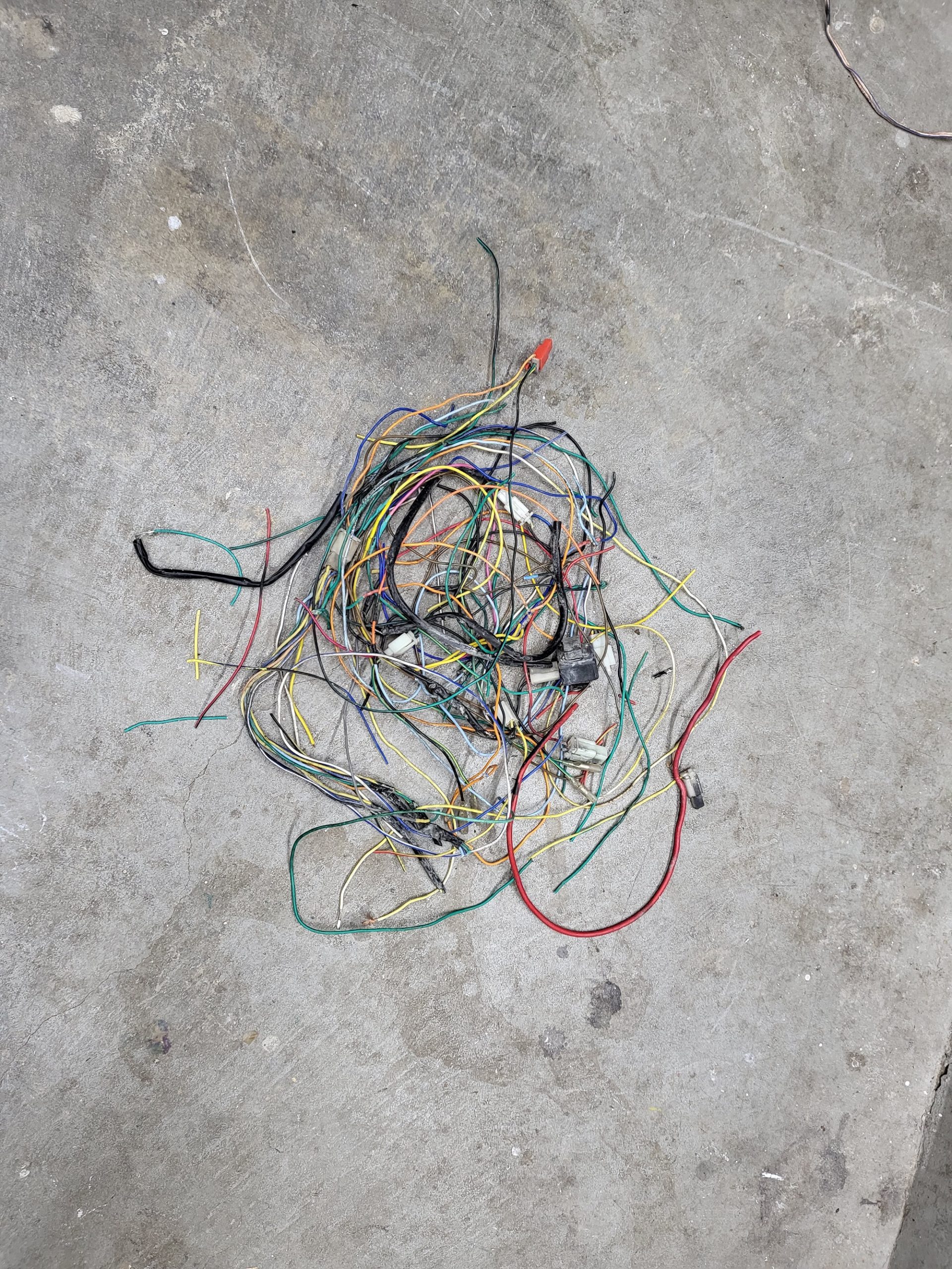
The first thing I wanted to clean up was the wiring. It was something I really neglected and it was pretty much a rat’s nest zip-tied together. I redid all the solder joints because the OEM’s work was very sloppy. This isn’t over, but it is a great start. I also removed anything that was not required to make it functional and street legal.
Original MessWhat Was RemovedCurrent
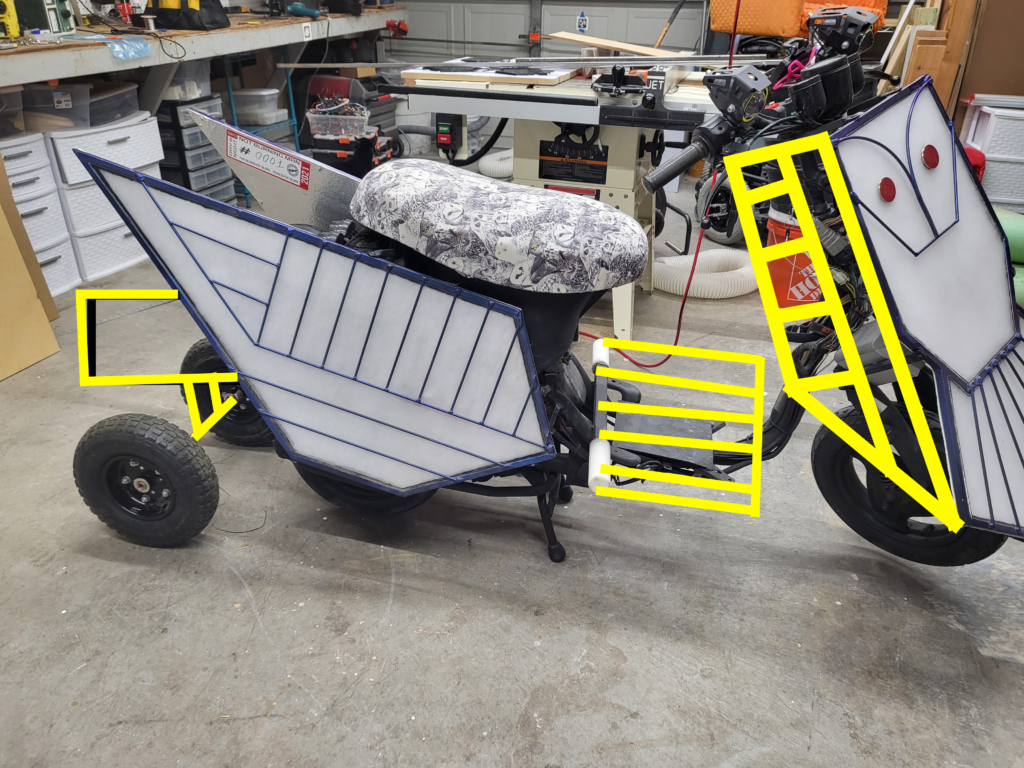
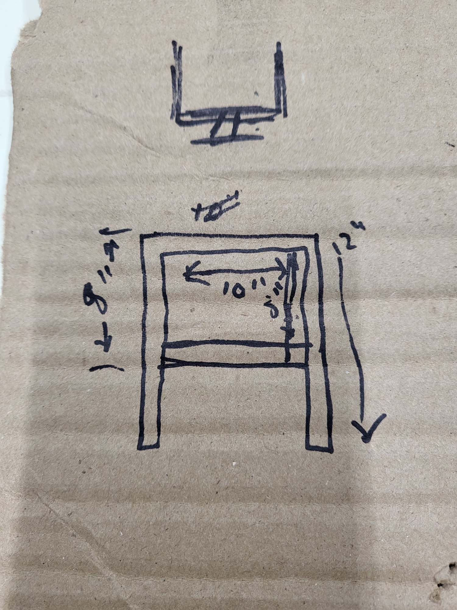
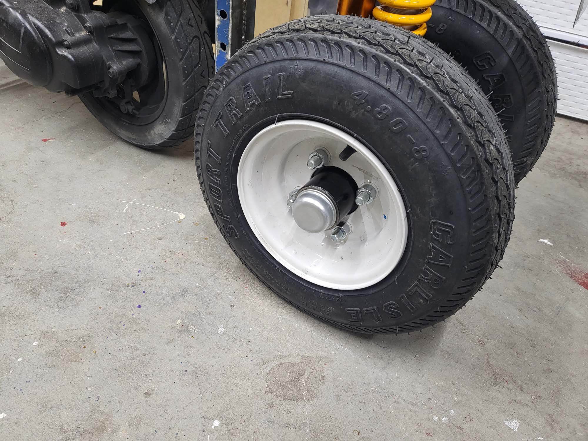
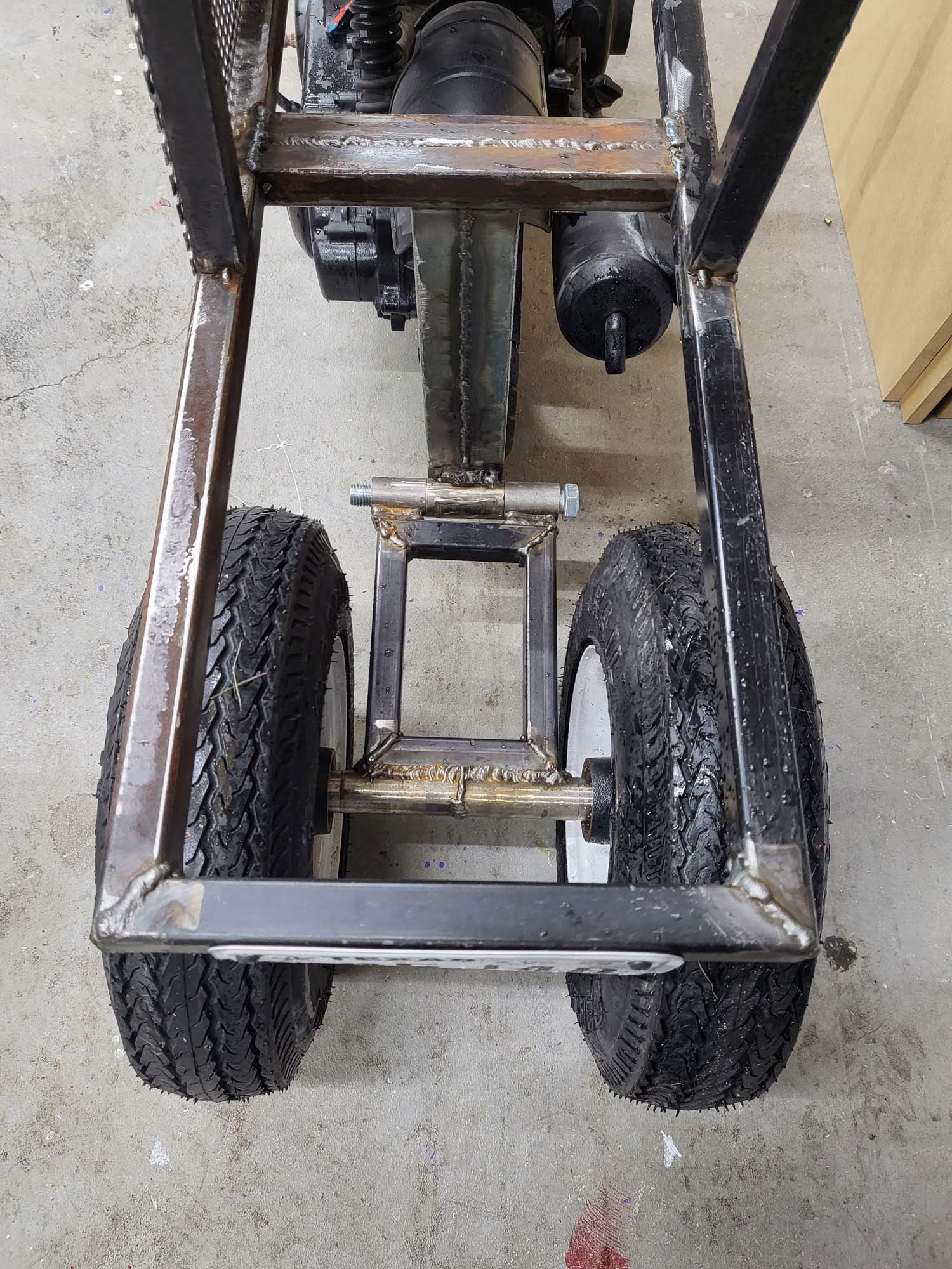
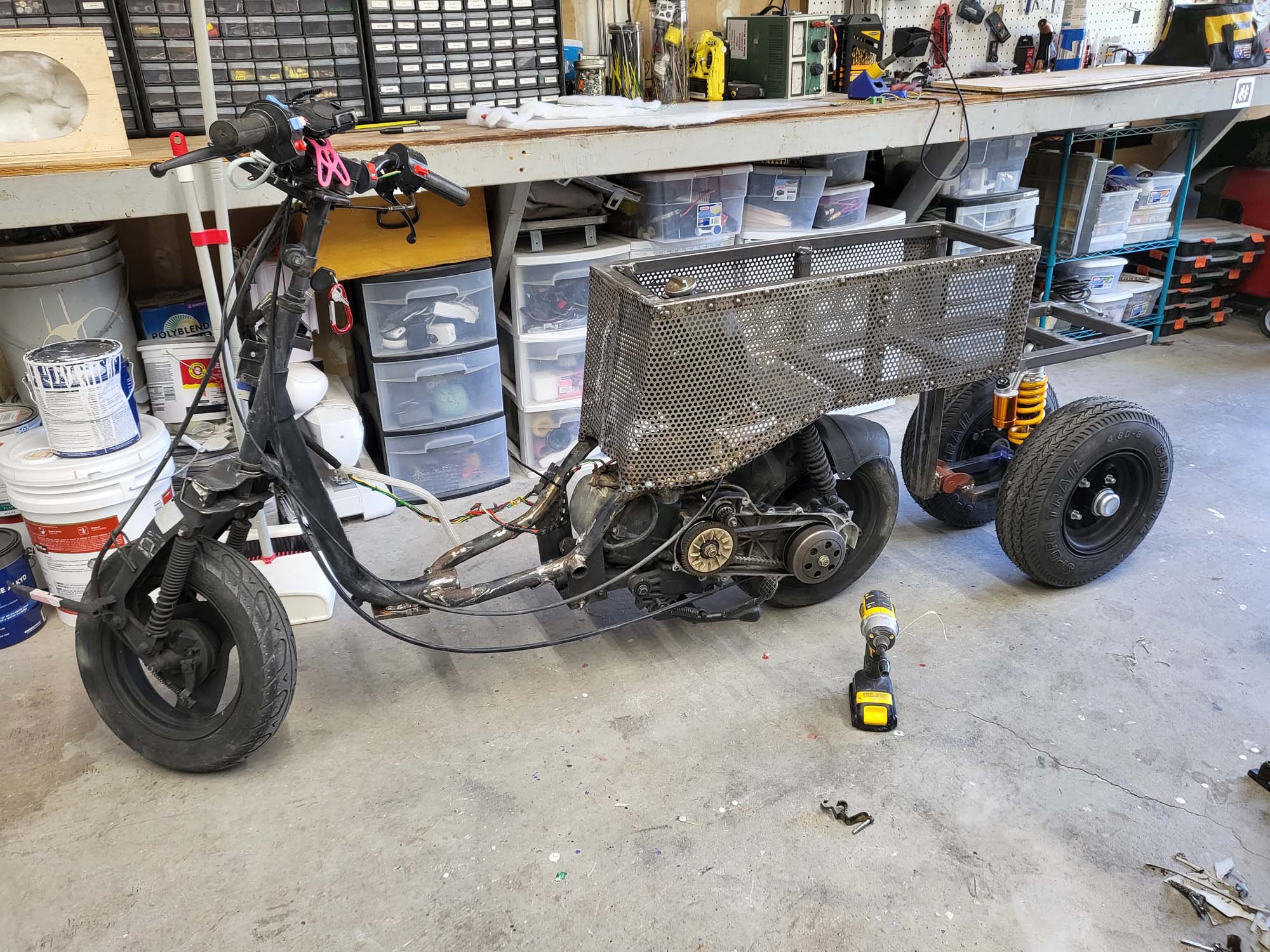
The plan is to extend the back and seat so that more people can fit comfortably. Under the back will be two 12 inch trailer wheels roughly a foot apart that keep the vehicle upright. I will have to build some type of suspension for it. I also need to build a panel for either side of the front forks. This is to hide the base vehicle more while looking at it from the side. I also want to build a better platform for the driver’s feet.
Rough Idea of What I Am Going For
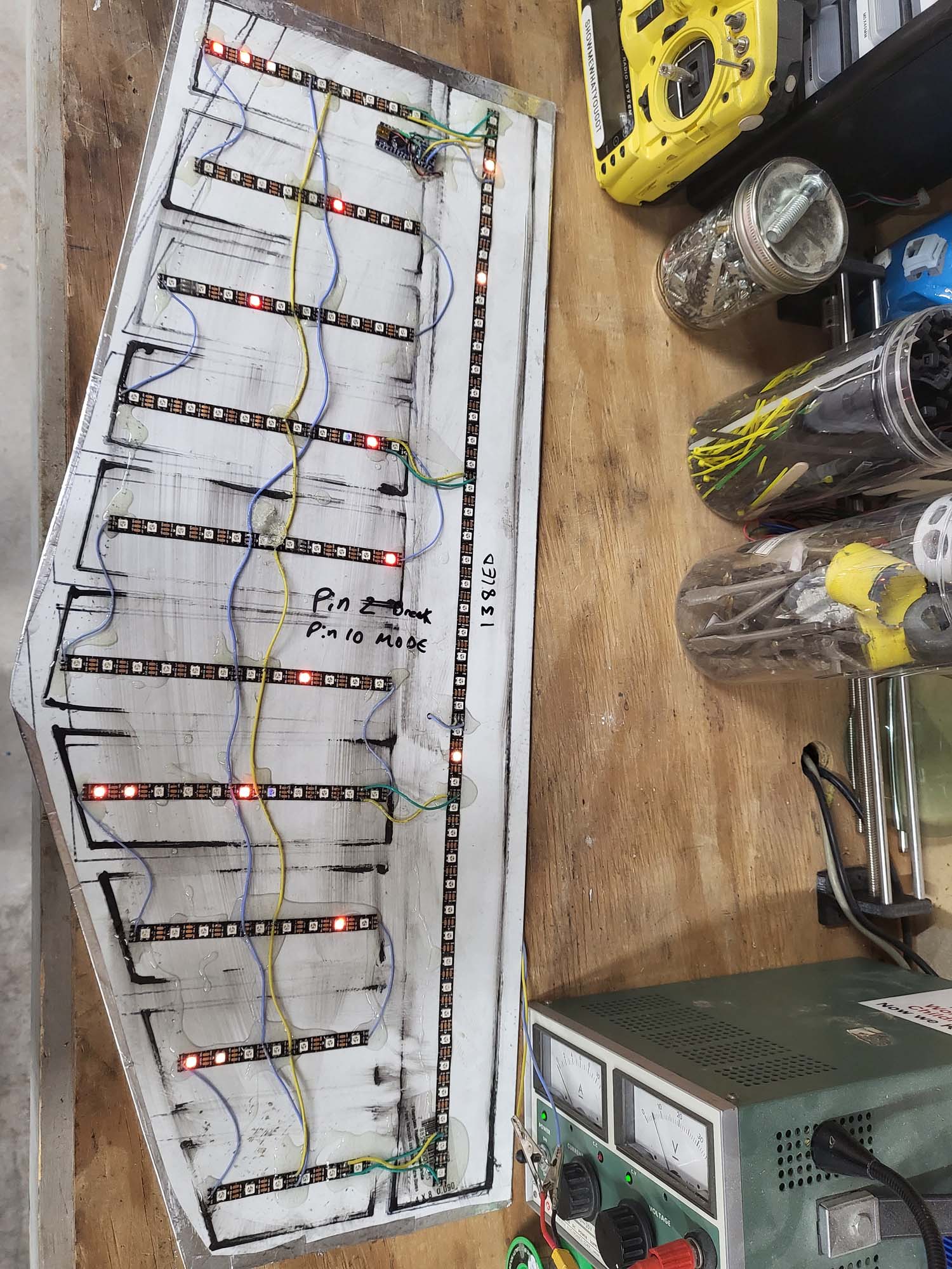
After cleaning up the wires, the next step was to build two more LED panels, one for either side of the front forks. I am starting to be able to knock these out fairly fast now.
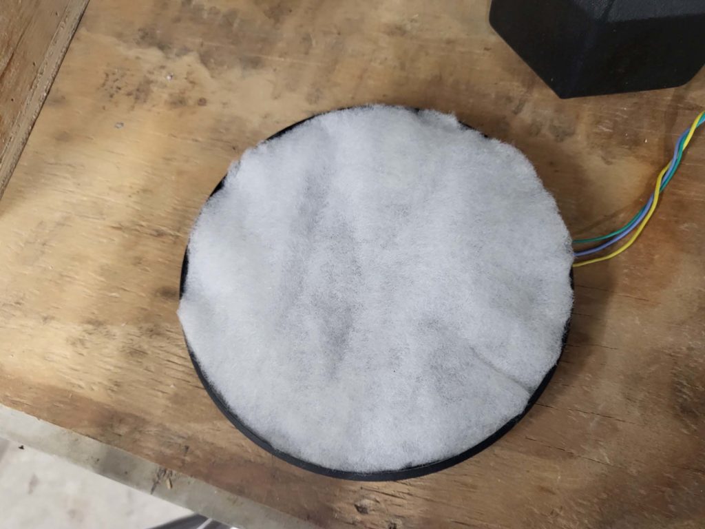
Here is a perfect example of how much better it looks with the Polyfil.
The color shift paint I was initially using was something I had on my shelf. After we decided to use it, I had a hard time finding it because the company discontinued it. When I did find a store that had it in stock, it was ridiculously expensive. I was experimenting with mica pigments for a separate epoxy project, and realized I could make it myself. I am using Eye Candy mica powders–a 5:1 mixture of their Geisha Doll and Sapporo.
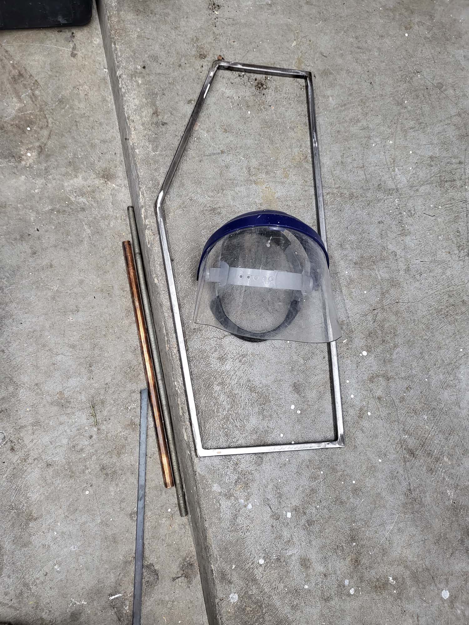
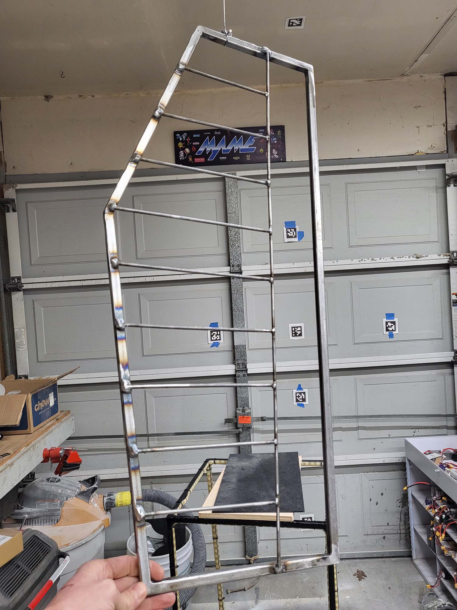
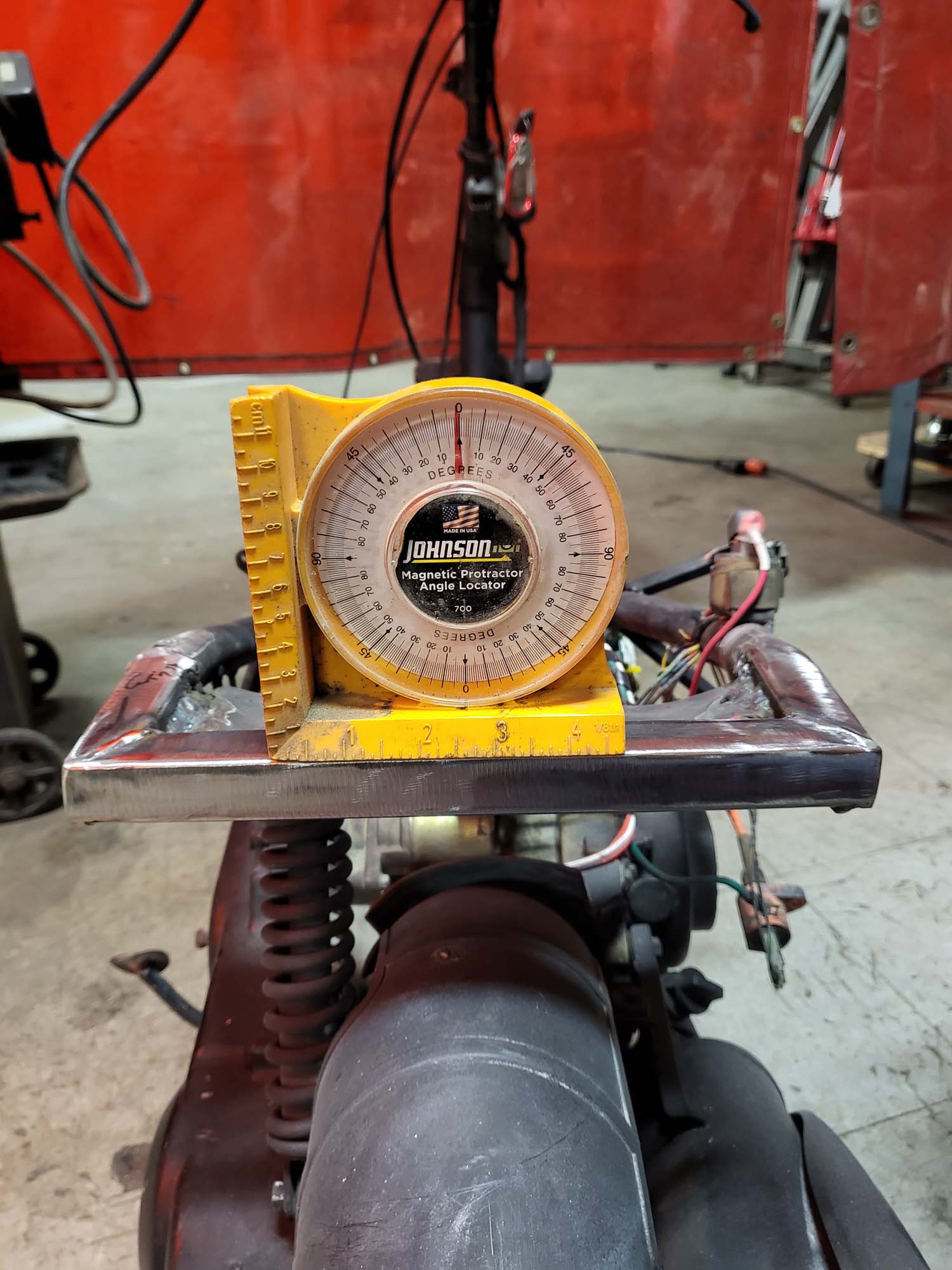
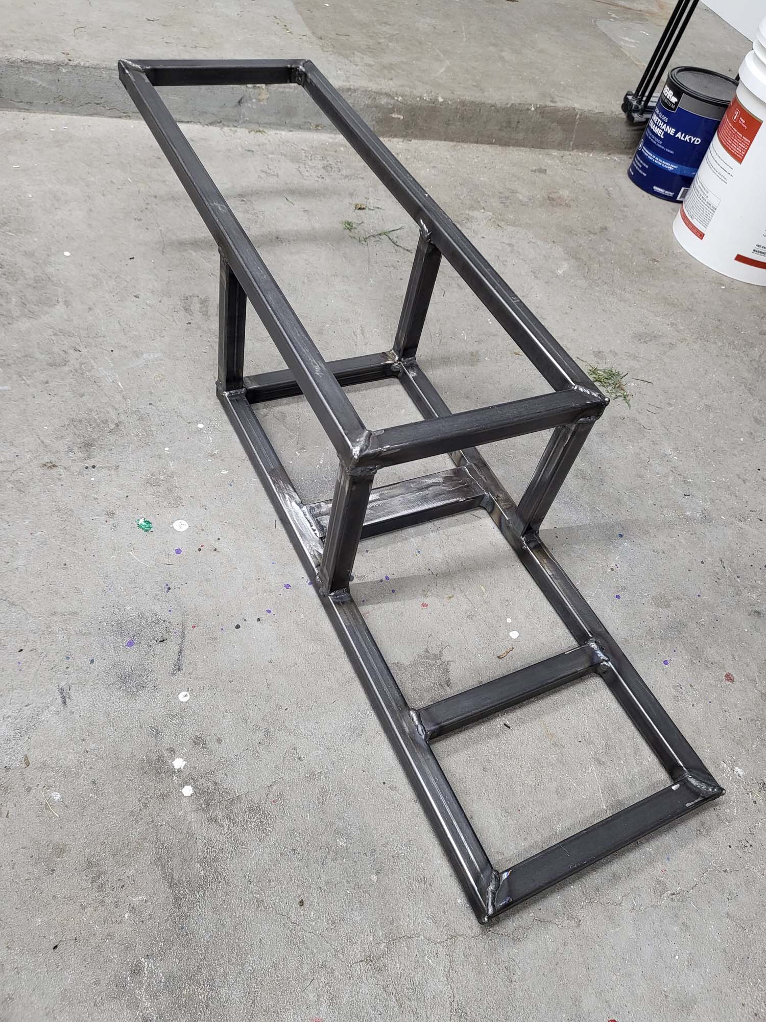
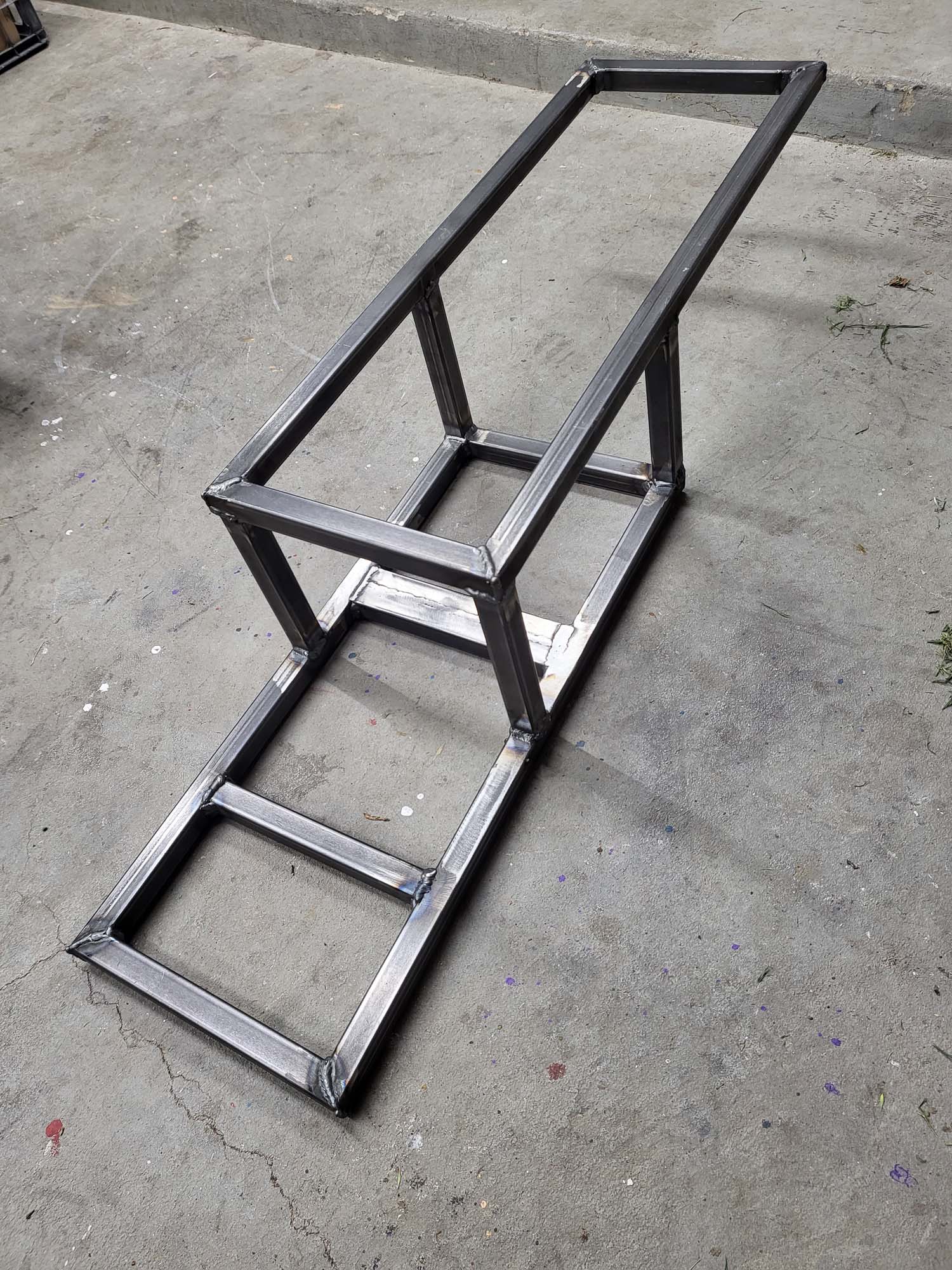
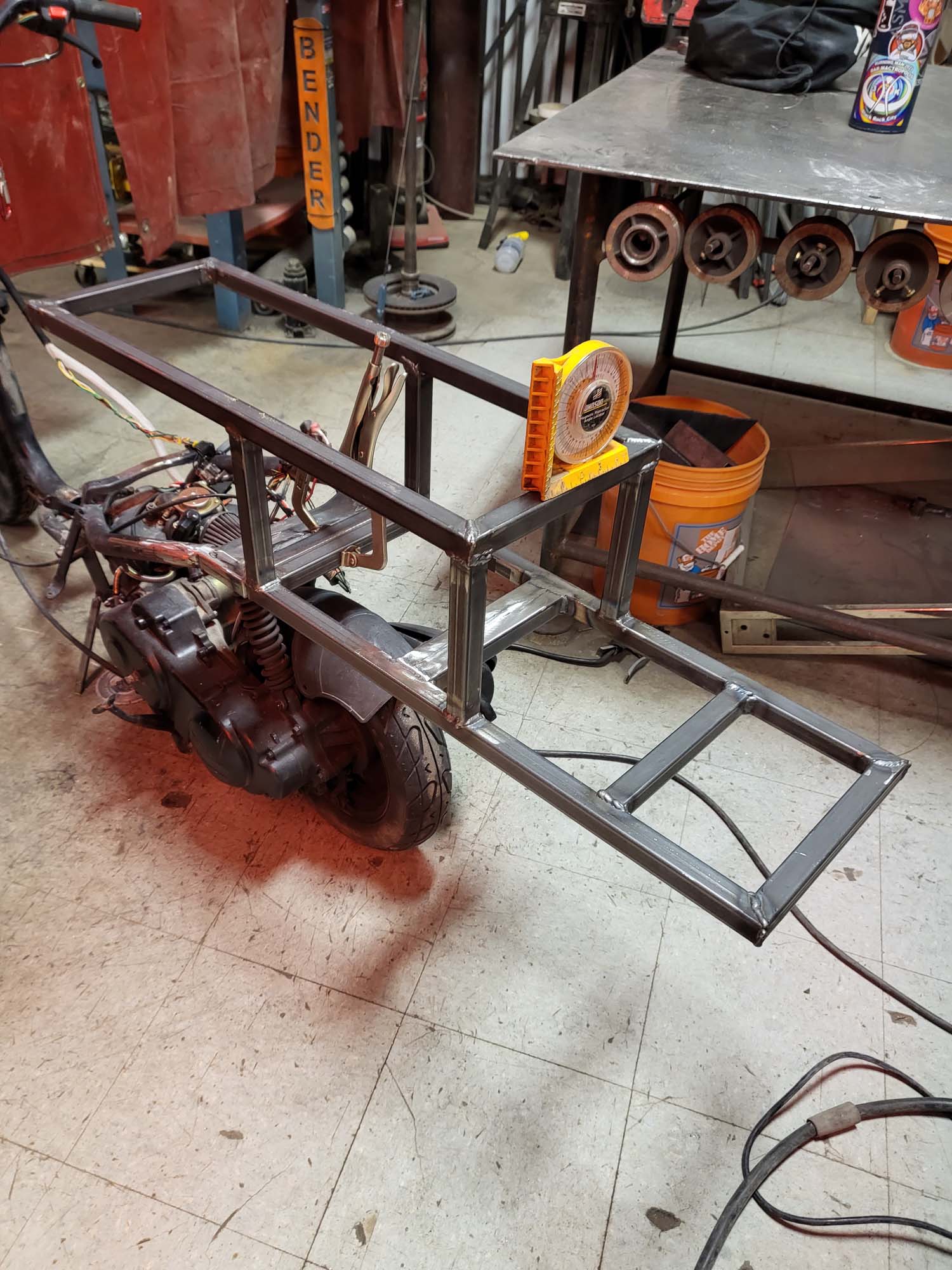
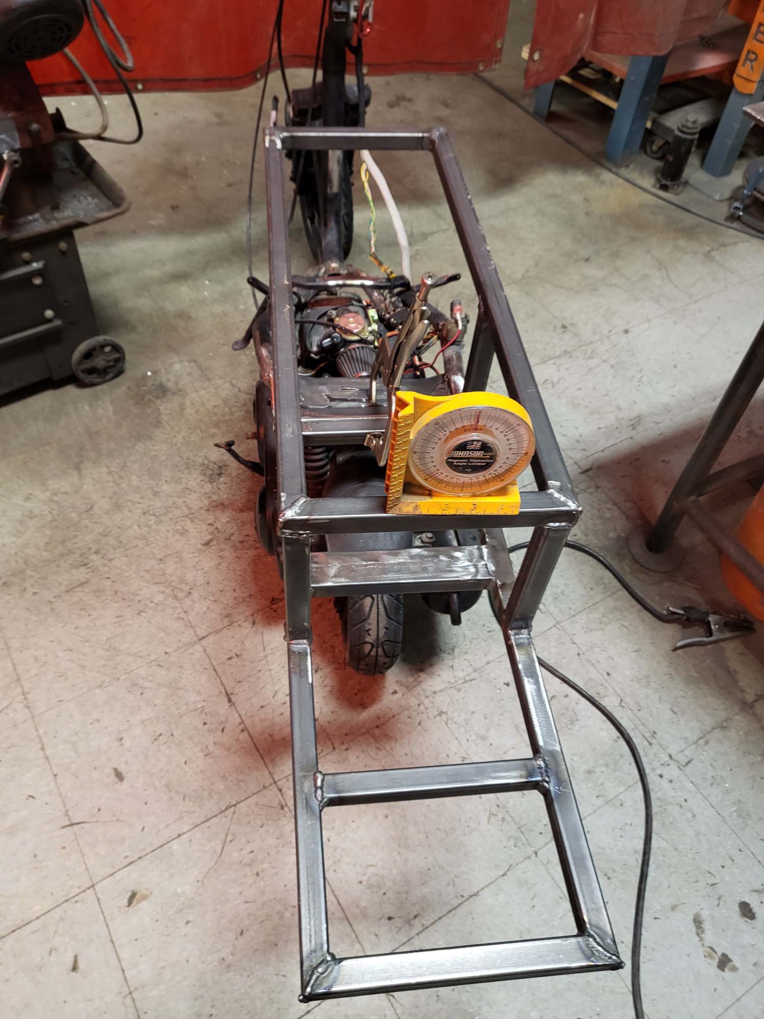
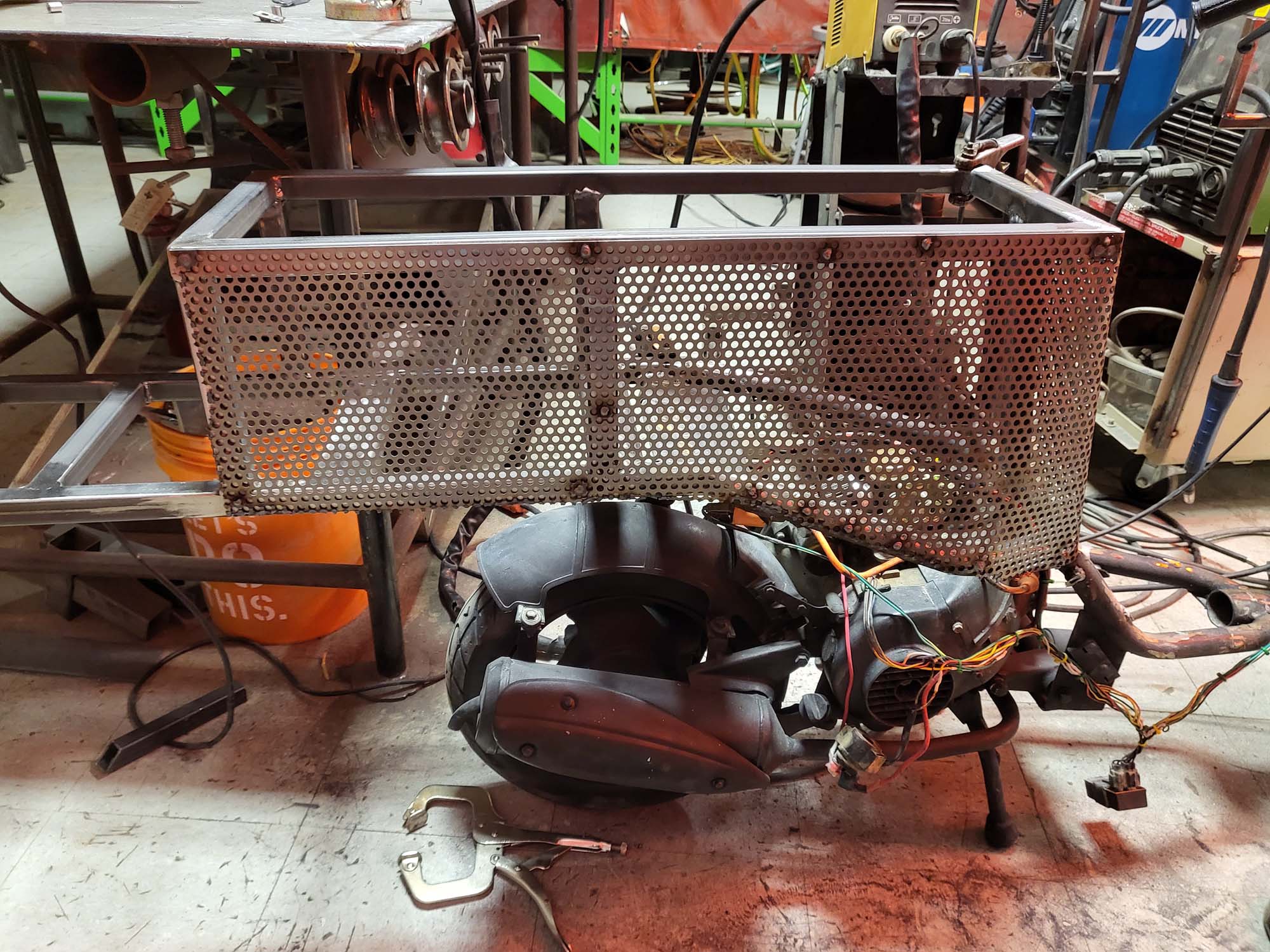
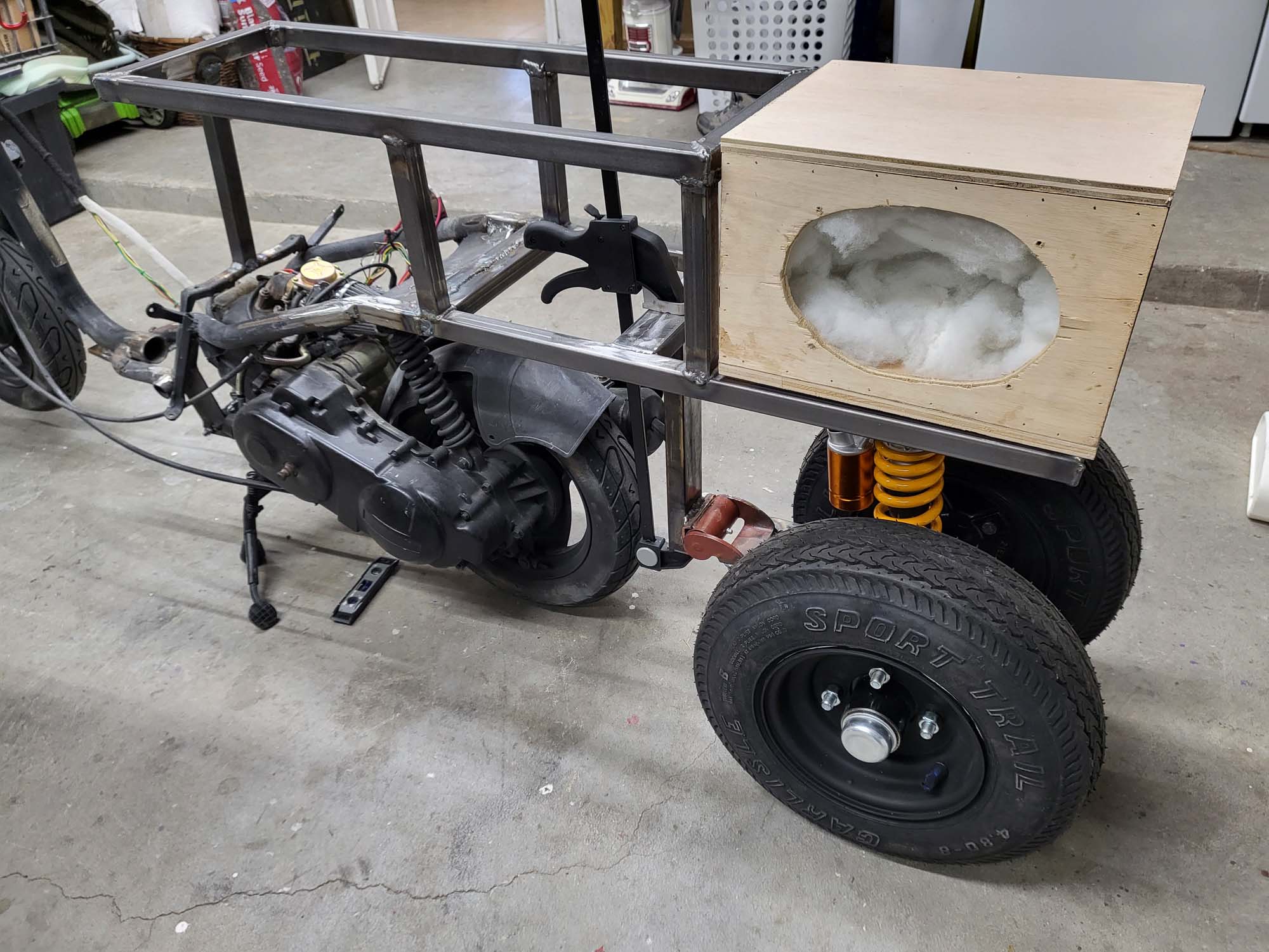
After the panels were done, I started to rebuild the frame. I used one-inch square tubing for the new sections of the frame. The first step was to remove as much of the frame as possible and weld a piece of one-inch square tubing to the frame to give myself a good mounting point.
I built the new section of the frame off the bike so I could make everything as square and parallel as possible. Doubled up the tubing where the new section mounts to the old frame and for the rear suspension.
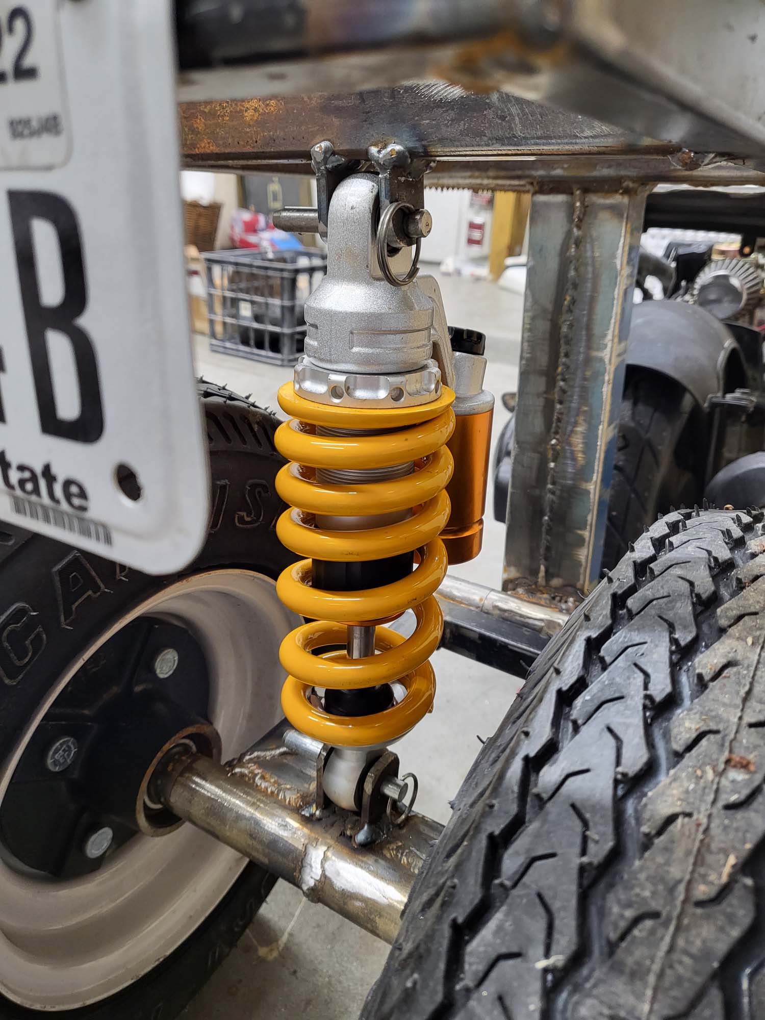
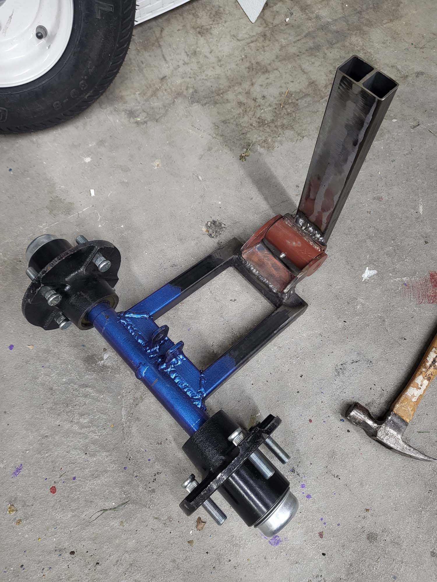
I had to design suspension for the two trailer wheels on the back. This was something new to me and I went through a few iterations. I asked a some experts what they thought… Some suggested a swing arm and others said to mount it rigid but slightly off the ground. I went with the swing arm idea.
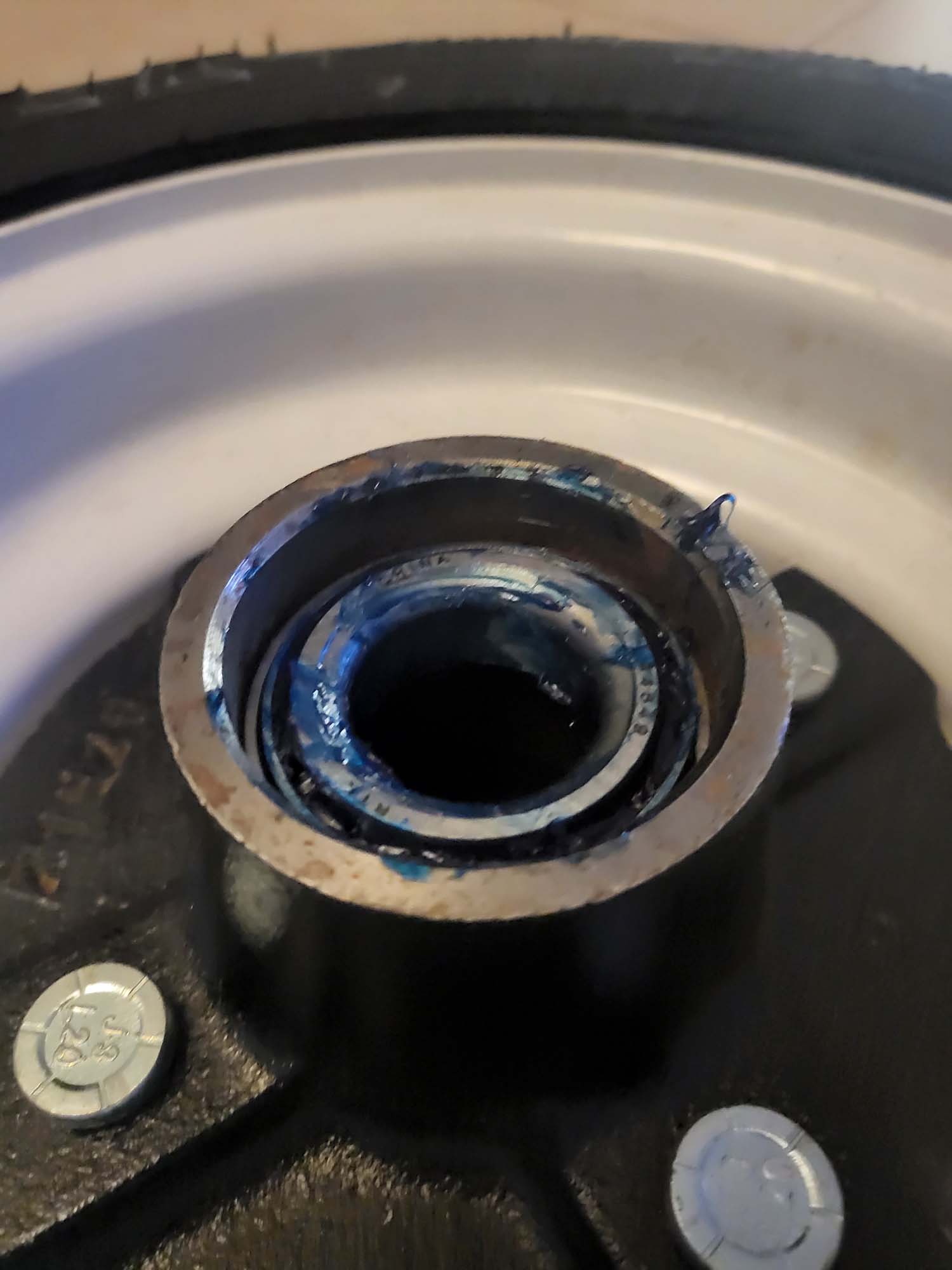
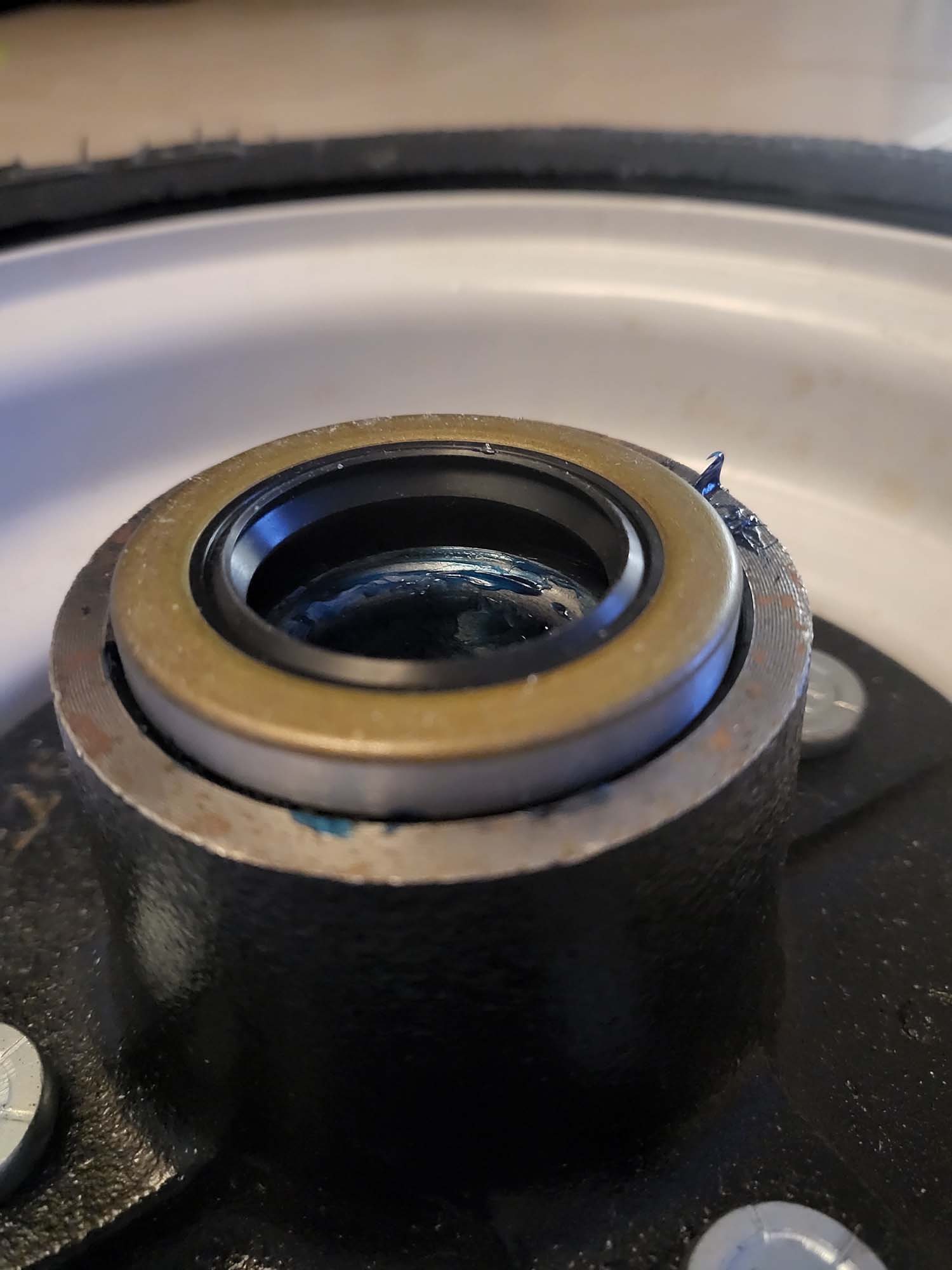
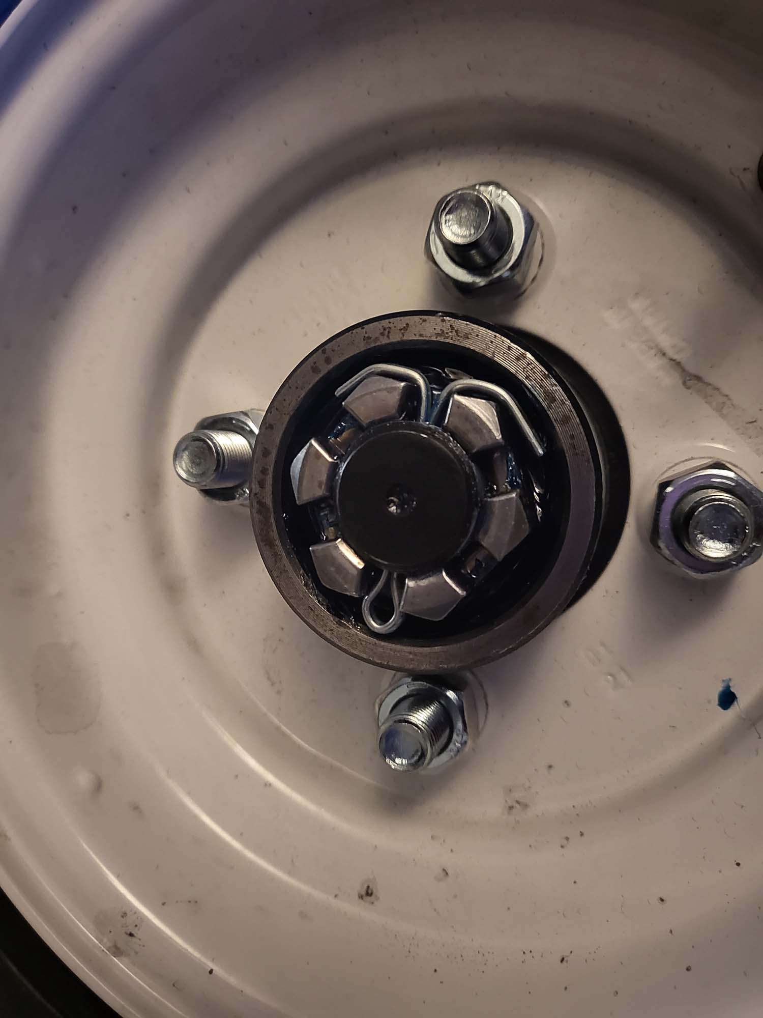
I ordered trailer hubs kits from Trail Parts USA. They were worth every penny and saved me so much time on the lathe. I tried a couple of different hedges. Honestly, I may come back to this because the current hinge has too much slop but I want to finish up the rest of the current tasks.
Original MeasurementsGreasing Up The BearingHub SealCrown NutHub CapAssembled1st HindgeThis Shock Is Too Stiff2nd Hindge
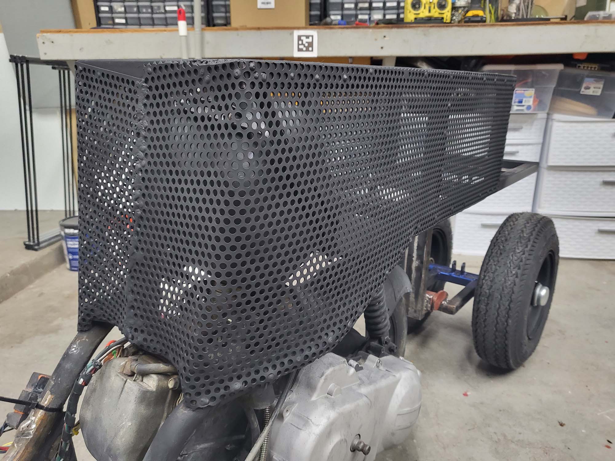
Now that everything is framed I wanted to enclose it to create storage in the seat. My work gave me a few sheets of this steel with holes in them. I still have to add the bottom pieces… that is in my to-do list below.
One Side DoneBoth Sides DoneBase Paint
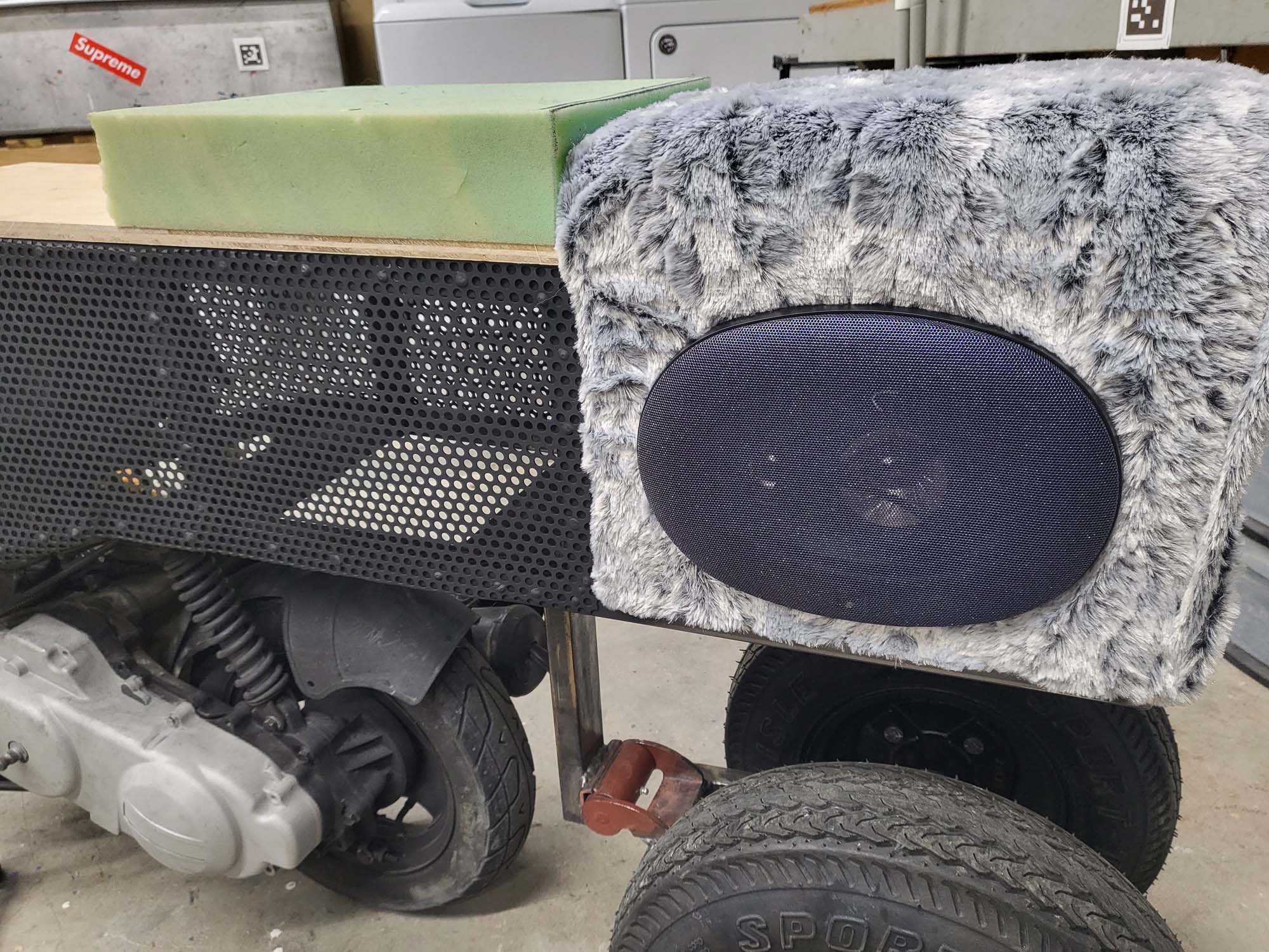
The sound system in version 1 consisted of a bunch of cheap junk I picked up from Goodwill. They did not sound that bad but I wanted something that fit ascetically with the design. I am using marine grade equipment due to the corrosive nature of the Playa dust. There is a 3-way 6×9 on either side of Hootie. These are powered by a 300-watt Velex Powersport Class D Amplifier.
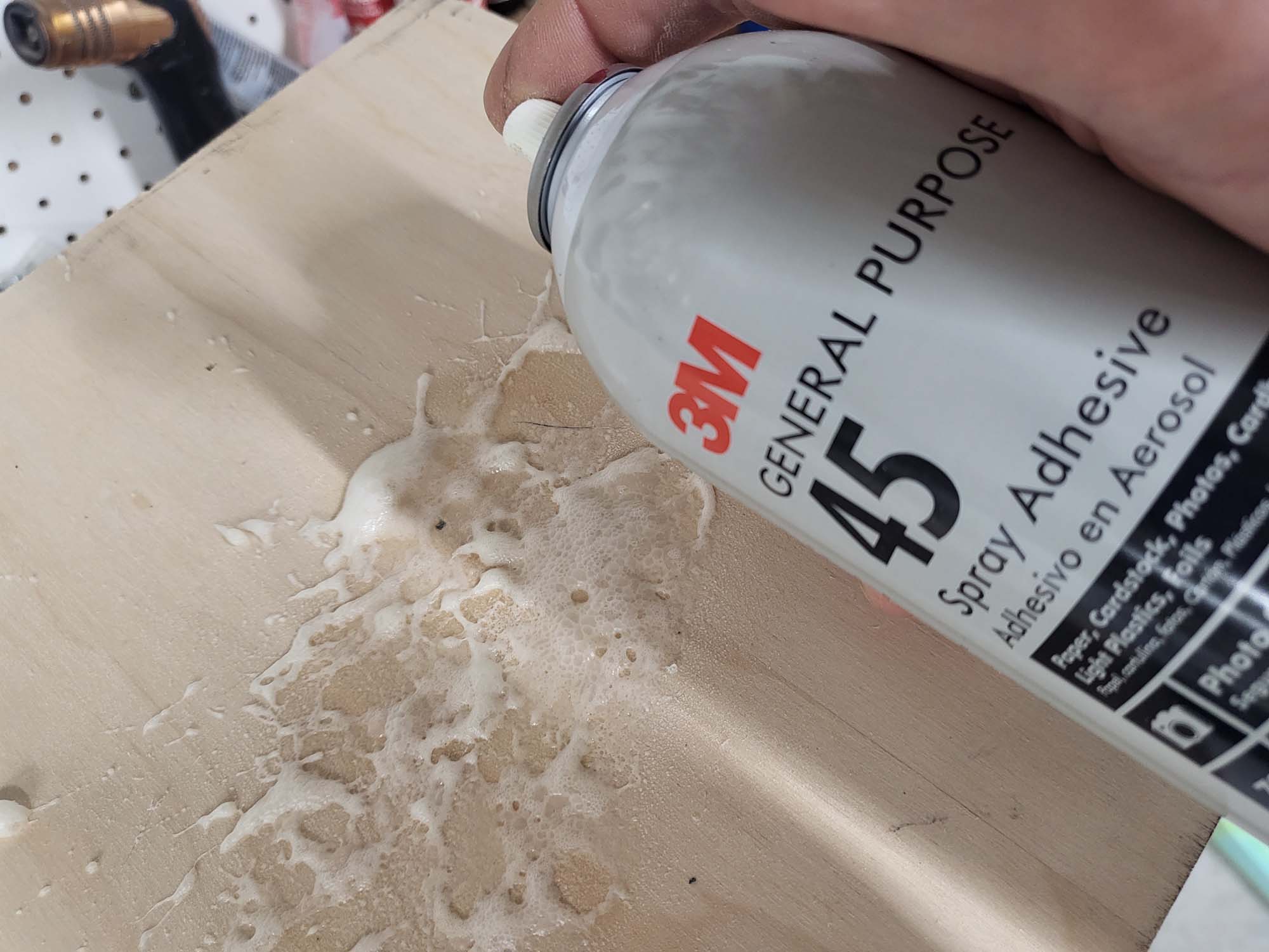
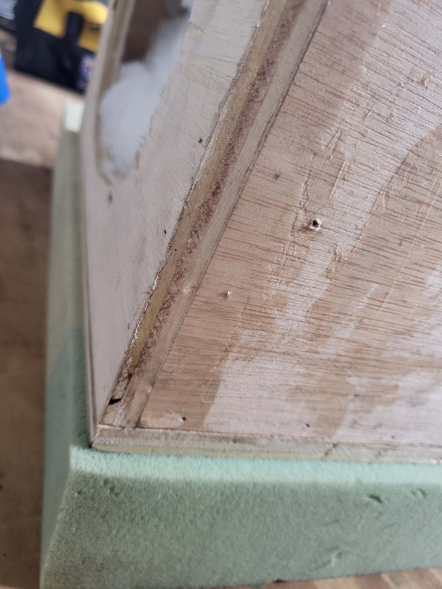
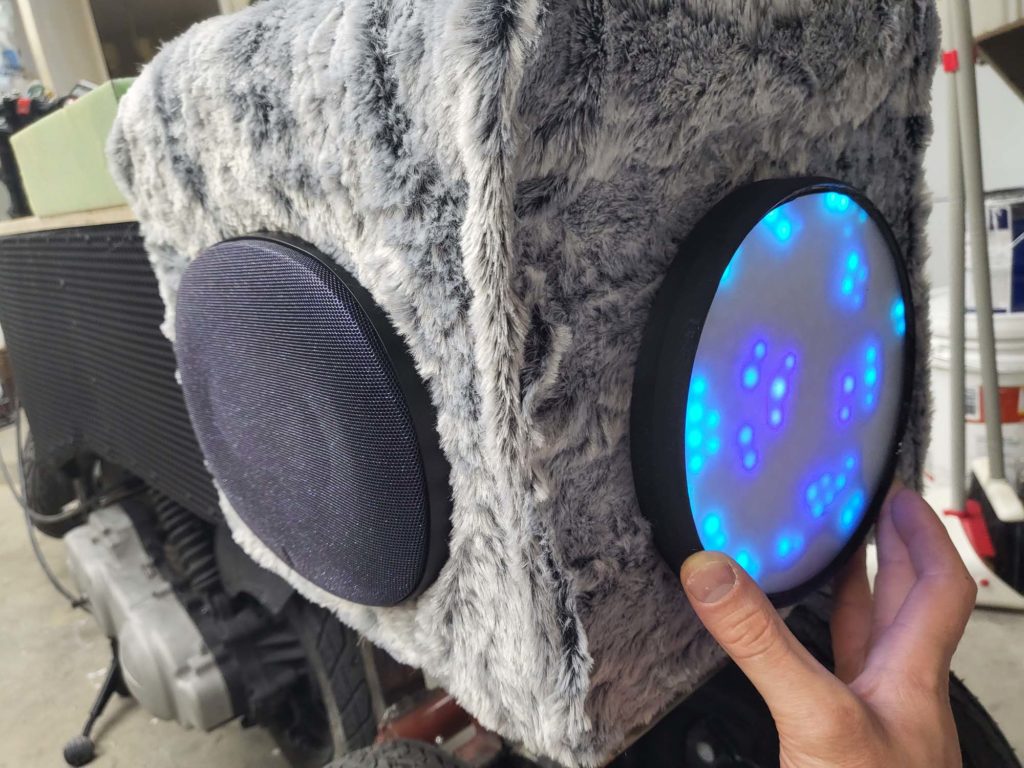
Built The BoxGlueing Foam & Fux FurFoam Makes It A SeatI’m Gonna Fix The Top Left CornerAll Sparkle No Pony
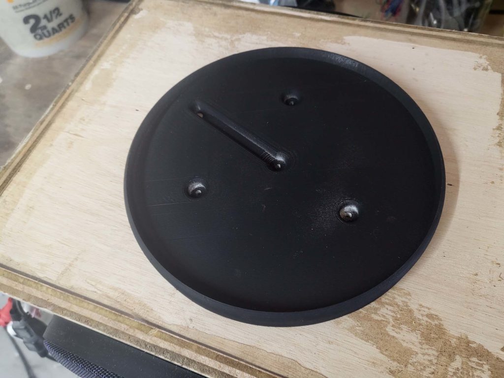
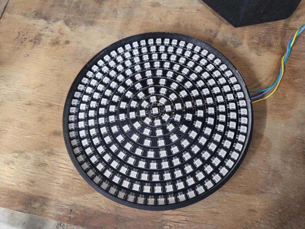
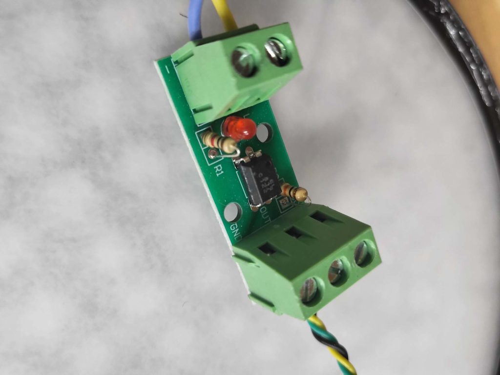
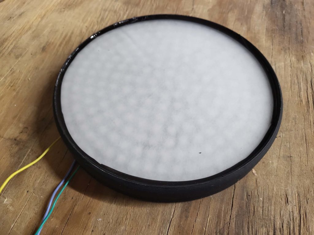
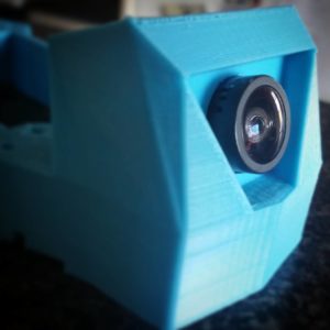
Hootie V2 has just over 1,200 individually addressable LEDs. Each side of the vehicle has a minimum of 240 LEDs. The back LED panel doubles as a brake light. When the vehicle’s brake engages, all 241 LEDs instantly turn red. The front of the vehicle has headlights with high and low beams.
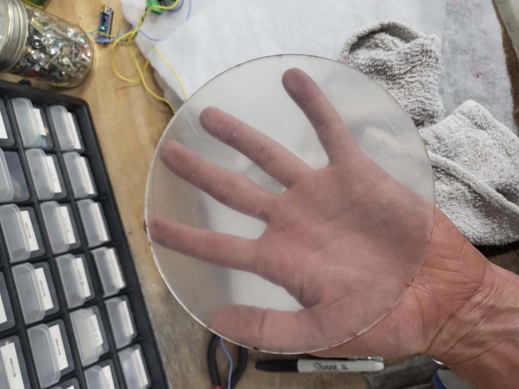
Painted The 3D Print241 LED RingGot To Have The PolyLaser Cut AcrylicSanded FrostedOptocoupler Isolation Siliconed In PlaceGonna Go Here
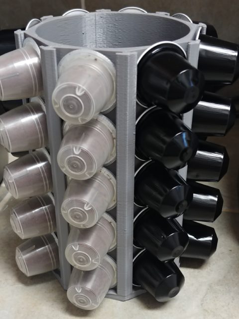
I needed a new holder for the office and decided to design one instead of print one that was already available. The holder can hold 40 pods total and can house spoons in the middle.
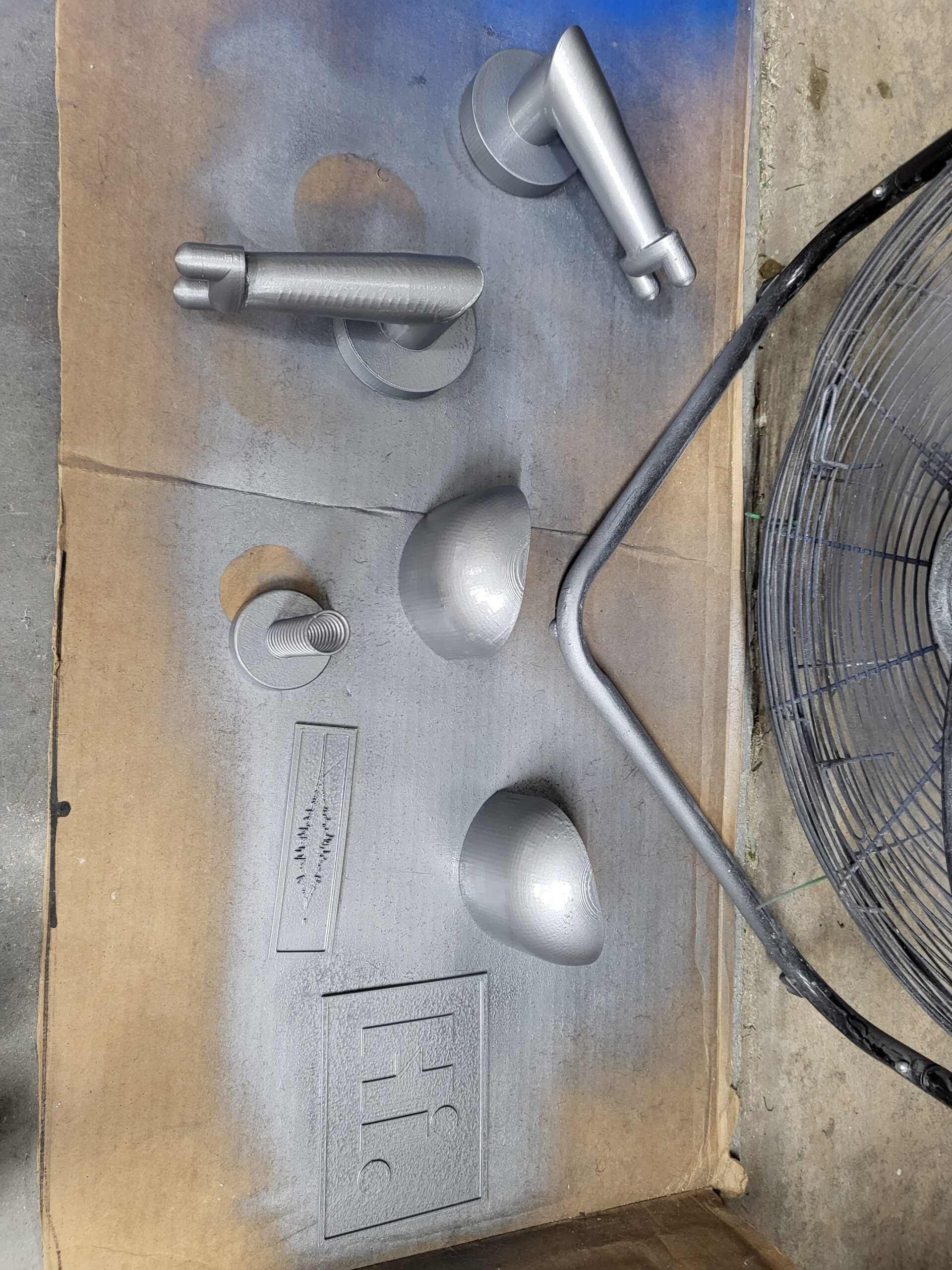
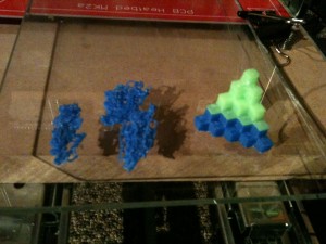
I have been 3D printing test objects for the past few weeks and my progress is getting better after each object I print. The main variable in successfully printing a quality object is making sure the heated bed is level to the print head. The first object I tried printing was the 5mm Calibration Cube Steps:
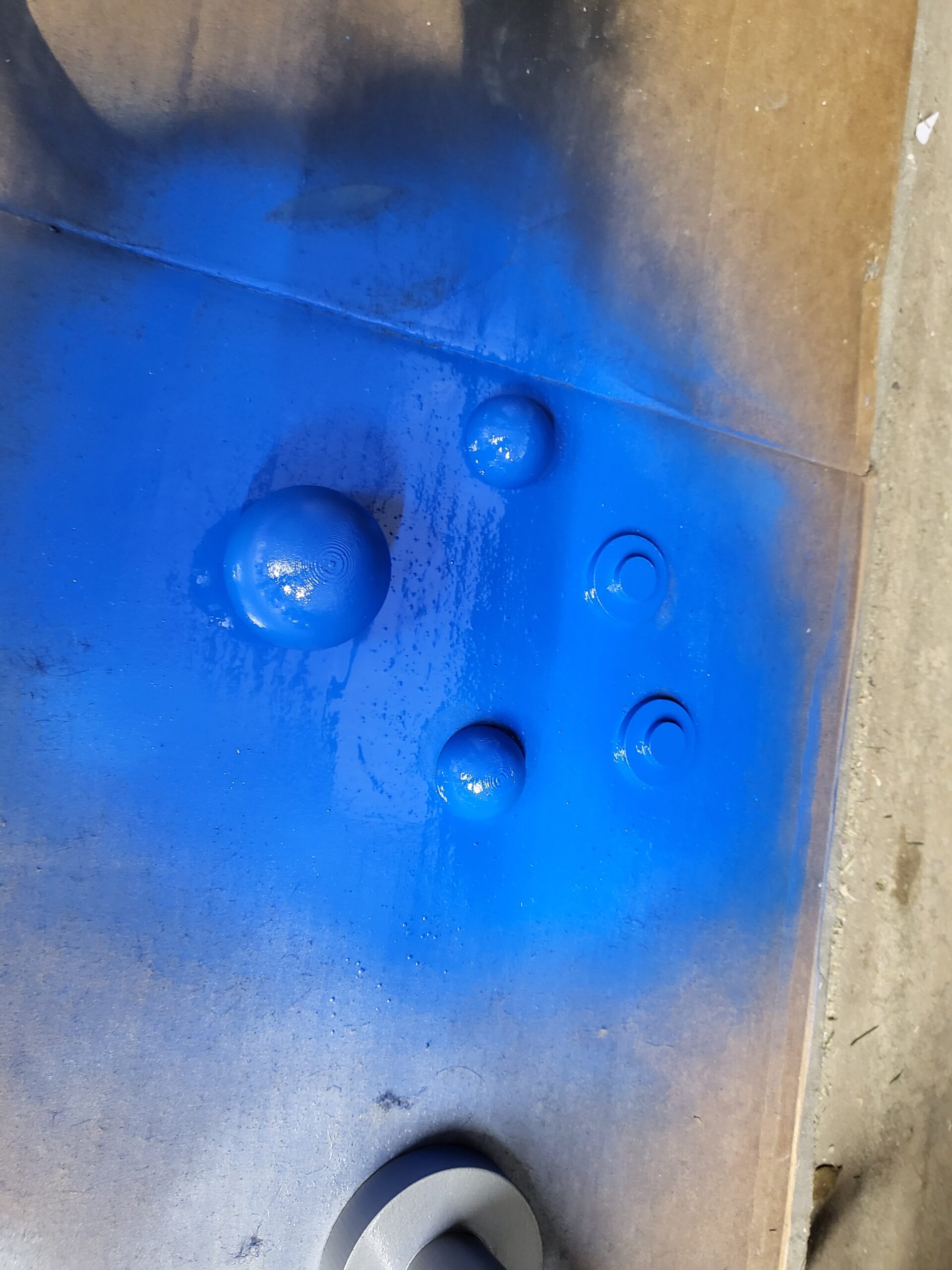
These were the 1st, 2nd & 3rd Print:
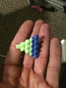
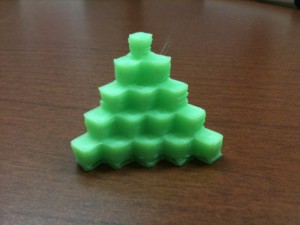
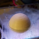
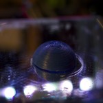
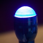
The qbert design is one of the first 3d printing test objects most people print because it is extremely helpful in calibrating each axis. Each cube in the design should be 5MM3. Once the object is printed, I used a digital caliper to validate that each axis is moving (printing) the correct distances. After I correctly calibrated the axes; I printed my second calibration object: the dome.
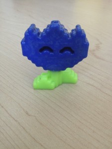
After calibrating using the 3D printing test objects, I started printing and designing more practical objects. The 1st was a gift to my wife, Knap’s Mario Flower:
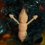
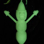
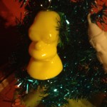
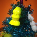
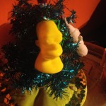
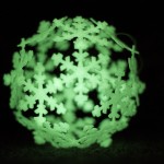
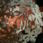
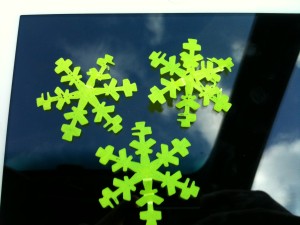
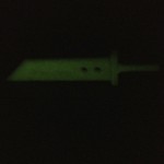
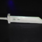
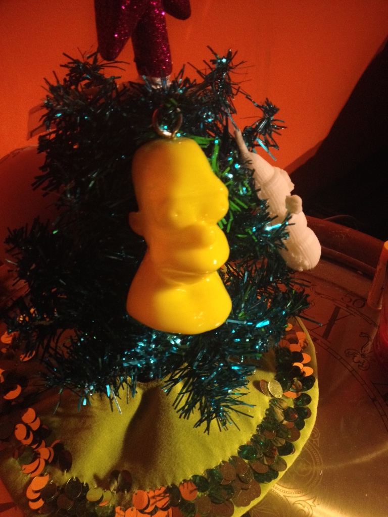
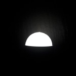
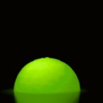
Thingiverse had an ornament contest and I wanted to get involved, so I designed a 3D model of MR.Hanky the Christmas Poo. This was my first design that I printed and I tell you, it is a weird feeling designing something in software then printing it off a few hours later. We are absolutely living in the future. I uploaded the model to my Thingiverse profile so you can download and print it yourself.
White Mr Hanky
Glow In The Dark
For Christmas, I printed off a Homer bust for my bother:
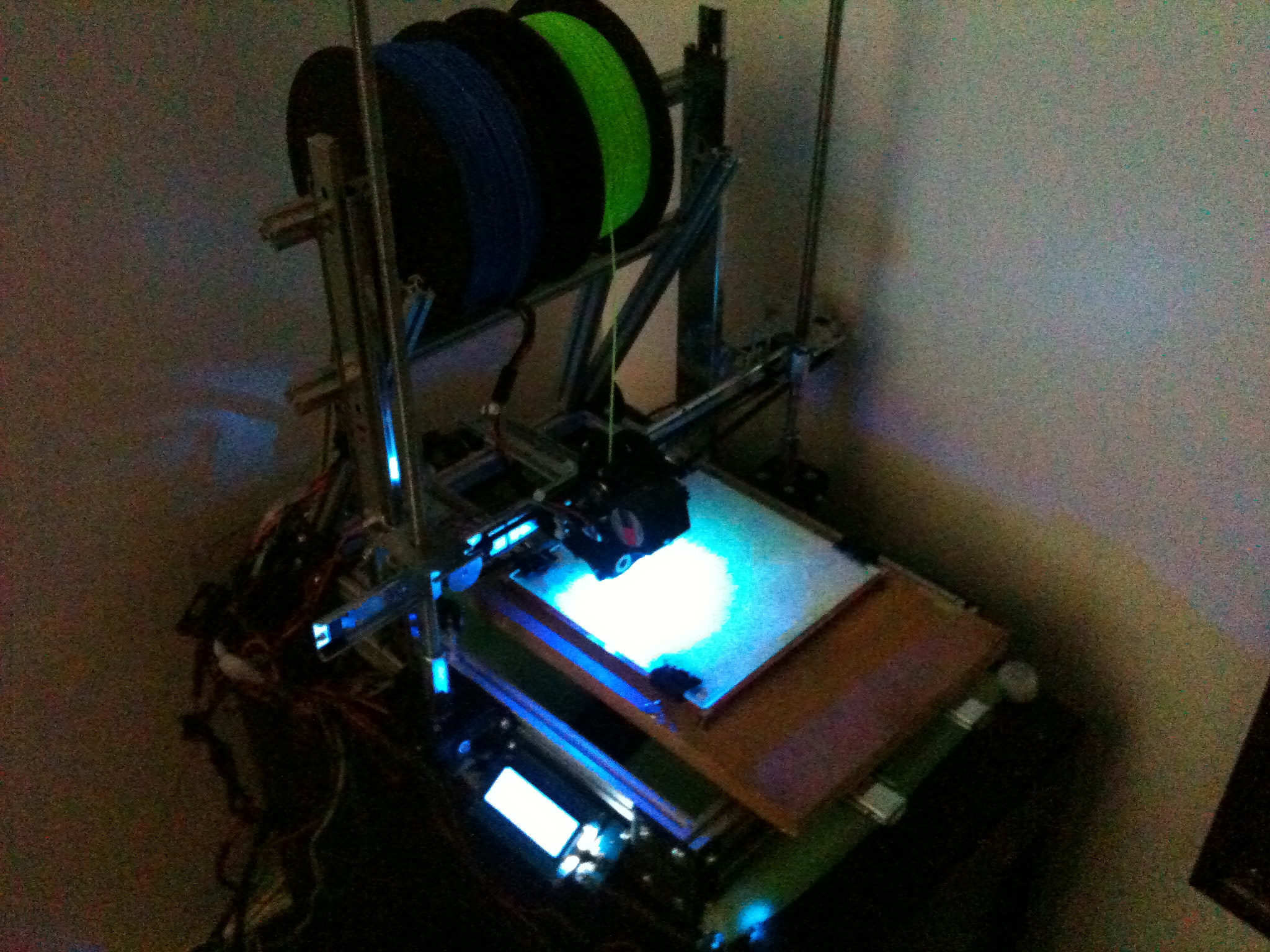
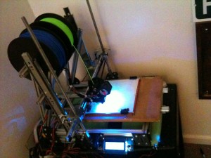
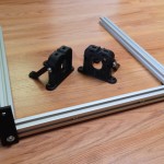
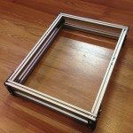
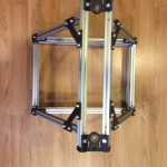
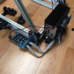
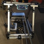
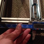
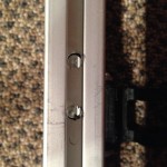
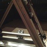
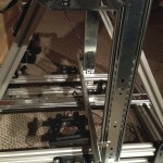
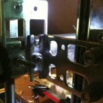
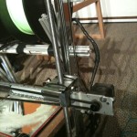
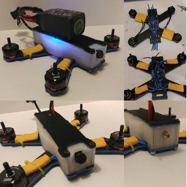
After pricing out the parts needed to finish the MindelMax 1.5 3D printer designand realizing I want to use rail slides instead of linear bearings and rods, I decided to develop a custom design. This post includes photos and descriptions from the alpha stage of the design. I am finalizing the bata design right now and a lot of what you see in this post has been changed. After a few more tests I will be releasing the design with an open source.
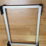
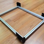
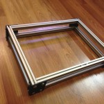
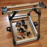
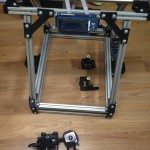
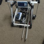
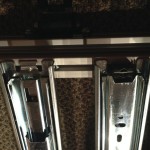
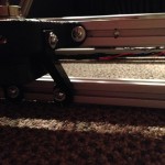
The current 3D printer design is limited to the 200mm by 200mm hotbed, but in the final design the x-axis has 300mm of printing range. The y-axis will be much larger; I am aiming for 600 to 800mm, but the design could theoretically support double or triple that. After deciding on the rails, I started measuring and drilling holes to accommodate them. I started with the y-axis; the y-axis holds the hot bed and the entire bed moves on two rails. I then moved to the z-axis, with a rail on each side (this might change). I used a M10 coupler bolt as a coupler for the threaded rods and stepper motor.
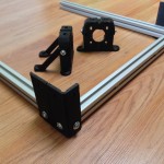
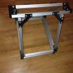
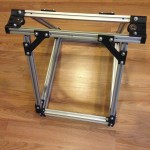
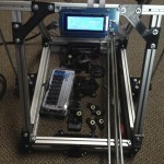
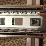
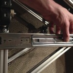
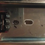
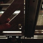
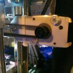
X-Axis:
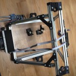
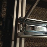
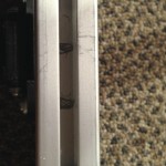
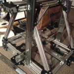
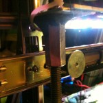
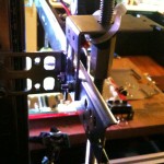
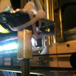
Each bracket has to mount a z-axis coupler bolt, a mount for one side of the x-axis rail, a mount for a z-axis rail, a hole for a bearing on the left bracket and a stepper motor mount on the right. Before I could print the new 3d printer design parts, I had to mock them up with random metal parts I had. I used my drill press to drill out the hole for the threaded rods and holes to mount the separate pieces together. I used SteelStik Epoxy Putty to hold a M10 coupler bolt to the bracket. These pictures were taken right before finalizing the beta version of the brackets. This was a good thing because the brackets were falling apart, hence the zip ties.


 Thingiverse had